


Functions Common to all the Control Modes
12
CFW700 | 12-19
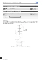
The
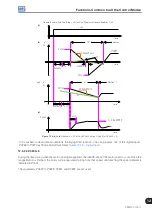
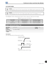
presents the DC braking operation via general disabling. This condition does only work in the V/f
scalar mode.
P0300
Time
+24 V
Motor Speed
Dead
Time
Open
DIx - General
Enable
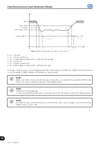
Figure 12.10:
DC braking operation via general disabling – V/f mode
For the V/f scalar control mode there is a “dead time” (motor rotates free), before starting the DC braking. This
time is necessary to the demagnetization of the motor and it is proportional to its speed.
During the DC braking the inverter indicates the “RUN” status at the keypad (HMI).
During the braking process, if the inverter is enabled, the braking is interrupted and the inverter will operate
normally again.
ATTENTION!
The DC braking may continue active after the motor has already stopped. Be careful with the motor
thermal sizing for short period cyclic braking.
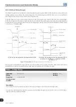
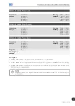
P0301 – DC-Braking Speed
Adjustable
Range:
0 to 450 rpm
Factory
Setting:
30 rpm
Properties:
V/f, VVW and Sless
Access groups
via HMI:
Description:
This parameter establishes the beginning point for the DC braking application at stopping. Refer to the
and
Summary of Contents for CFW700
Page 2: ......
Page 4: ......
Page 8: ...Summary...
Page 34: ...2 General Information 2 4 CFW700...
Page 38: ...3 About the CFW700 3 4 CFW700...
Page 56: ...7 Starting up and Settings 7 4 CFW700...
Page 58: ...8 Available Control Types 8 2 CFW700...
Page 78: ...10 VVW Control 10 8 CFW700...
Page 158: ...13 Digital and Analog Inputs and Outputs 13 28 CFW700...


