Functions Common to all the Control Modes
12
CFW700 | 12-15
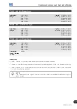
P0321 – DC Link Power Loss
Adjustable
Range:
178 to 282 V
308 to 616 V
308 to 616 V
308 to 616 V
308 to 616 V
Factory
Setting:
P0296 = 0: 252 V
P0296 = 1: 436 V
P0296 = 2: 459 V
P0296 = 3: 505 V
P0296 = 4: 551 V
P0322 – DC Link Ride-Through
Adjustable
Range:
178 to 282 V
308 to 616 V
308 to 616 V
308 to 616 V
308 to 616 V
Factory
Setting:
P0296 = 0: 245 V
P0296 = 1: 423 V
P0296 = 2: 446 V
P0296 = 3: 490 V
P0296 = 4: 535 V
P0323 – DC Link Power Back
Adjustable
Range:
178 to 282 V
308 to 616 V
308 to 616 V
308 to 616 V
308 to 616 V
Factory
Setting:
P0296 = 0: 267 V
P0296 = 1: 462 V
P0296 = 2: 486 V
P0296 = 3: 535 V
P0296 = 4: 583 V
Properties:
Vector
Access groups
via HMI:
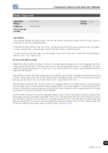
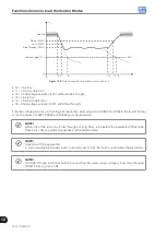
Description:
P0321 - defines the U
d
voltage level under which the line loss will be detected.
P0322 - defines the U
d
voltage level that the inverter will try to keep regulated, so that the motor keeps operating.
P0323 - defines the U
d
voltage level at which the inverter will identify the return of the line, and from where
the motor must be reaccelerated.
NOTE!
These parameters work together with the parameters P0325 and P0326 for the Ride-Through in
vector control.
Summary of Contents for CFW700
Page 2: ......
Page 4: ......
Page 8: ...Summary...
Page 34: ...2 General Information 2 4 CFW700...
Page 38: ...3 About the CFW700 3 4 CFW700...
Page 56: ...7 Starting up and Settings 7 4 CFW700...
Page 58: ...8 Available Control Types 8 2 CFW700...
Page 78: ...10 VVW Control 10 8 CFW700...
Page 158: ...13 Digital and Analog Inputs and Outputs 13 28 CFW700...

