


9
Scalar Control (V/f)
9-12 | CFW700
2. In case DC link overvoltage (F022) keeps happening during the deceleration, reduce the value of P0151
gradually or increase the deceleration ramp time (P0101 and/or P0103).
3. If the supply line is permanently at a voltage level that results in a DC link voltage higher than the P0151
setting, it will not be possible to decelerate the motor. In this case, reduce the line voltage or increase the
value of the P0151 setting.
4. If, even with the procedures above, it is not possible to decelerate the motor in the necessary time, use the
dynamic braking (Refer to the
).
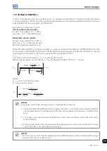
P0152 – V/f DC Regulation Proportional Gain
Adjustable
Range:
0.00 to 9.99
Factory
Setting:
1.50
Properties:
V/f and VVW
Access groups
via HMI:
Description:
It defines the DC Link Voltage Regulator proportional gain (refer to the
).
P0152 multiplies the DC link voltage error, i.e., Error = actual DC link voltage – (P0151), and it is normally used
to prevent overvoltage in applications with eccentric loads.
9.5 START-UP IN THE V/f CONTROL MODE
NOTE!
Read the whole CFW700 user's manual before installing, powering or operating the inverter.
Sequence for installation, verification, powering and start-up:
1. Install the inverter:
according to the chapter 3 - Installation and Connection, of the CFW700 user's manual,
wiring all the power and control connections.
2. Prepare the inverter and apply power:
according to the section 5.1 - Prepare for Start-Up, of the CFW700
user's manual.
3. Adjust the password P0000=5:
according to the
section 5.3 - Password Setting in P0000
, of this manual.
4. Adjust the inverter to operate with the application line and motor:
execute the Oriented Start-up
routine according to item 5.2.1 - Oriented Start-up Menu, of the CFW700 user's manual. Refer to the
, of this manual.
5. Setting of specific parameters and functions for the application:
program the digital and analog inputs
and outputs, HMI keys, etc., according to the application needs.
For applications:
That are simple, which can use the factory settings programming for the digital and analog inputs and outputs,
use the Menu “BASIC”. Refer to item 5.2.2 - Basic Application Menu, of the CFW700 user's manual.
That require only the digital and analog inputs and outputs with programming different from the factory settings,
use the Menu “I/O”.
That need functions as Flying Start, Ride-Through, DC Braking, Dynamic Braking, etc., access and modify
those functions parameters by means of the Menu “PARAM”.
Summary of Contents for CFW700
Page 2: ......
Page 4: ......
Page 8: ...Summary...
Page 34: ...2 General Information 2 4 CFW700...
Page 38: ...3 About the CFW700 3 4 CFW700...
Page 56: ...7 Starting up and Settings 7 4 CFW700...
Page 58: ...8 Available Control Types 8 2 CFW700...
Page 78: ...10 VVW Control 10 8 CFW700...
Page 158: ...13 Digital and Analog Inputs and Outputs 13 28 CFW700...


