


6
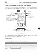
Inverter Model and Accessories Identification
6-2 | CFW700
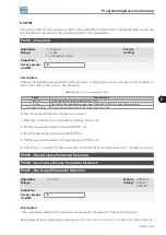
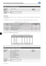
P0028 – Accessories Configuration
Adjustable
Range:
0000h to FFFFh
Factory
Setting:
Properties:
ro
Access groups
via HMI:
READ
Description:
Those parameters identify by means of a hexadecimal code the accessories that were found installed on the
control module.
The next table shows the codes shown in those parameters, regarding the main CFW700 accessories.
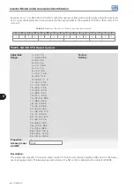
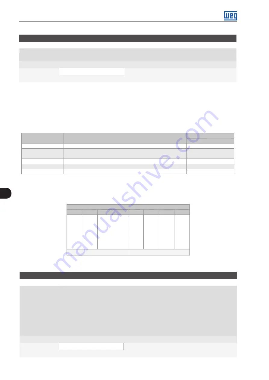
Table 6.1:
CFW700 accessory identification codes
Name
Description
Identification Code
P0028
RS-485-01
RS-485 serial communication module.
CE--
RS-232-02
RS-232C serial communication module with keys for programming the
microcontroller FLASH memory.
CC--
CAN/RS-485-01
CAN and RS-485 interface module.
CA--
CAN-01
CAN interface module.
CD--
MMF-01
FLASH Memory Module.
----
(1)
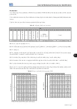
For the FLASH memory module, the P0028 identification code will depend on the combination of these
accessories, as presented in the next table.
Table 6.2:
Formation of the two first codes for P0028 parameter
Bits
7
6
5
4
3
2
1
0
∅
FL
A
S
H M
em
or
y
M
od
ul
e
∅
0
0
0
0
2
nd
Hexadecimal Code
1
st
Hexadecimal Code
(1)
Bit 6: indicates the presence of the FLASH memory module (0=without memory module, 1=with memory module).
P0029 – Power Hardware Configuration
Adjustable
Range:
Bit 0 to 5 = Rated Current
Bit 6 and 7 = Rated Voltage
Bit 8 = EMC Filter
Bit 9 = Safety Relay
Bit 10 = (0)24V/(1)DC Link
Bit 11 = (0)RST/(1)DC Link
Bit 12 = Dyn.Brak. IGBT
Bit 13 = Special
Bit 14 and 15 = Reserved
Factory
Setting:
Properties:
ro
Access groups
via HMI:
READ
Summary of Contents for CFW700
Page 2: ......
Page 4: ......
Page 8: ...Summary...
Page 34: ...2 General Information 2 4 CFW700...
Page 38: ...3 About the CFW700 3 4 CFW700...
Page 56: ...7 Starting up and Settings 7 4 CFW700...
Page 58: ...8 Available Control Types 8 2 CFW700...
Page 78: ...10 VVW Control 10 8 CFW700...
Page 158: ...13 Digital and Analog Inputs and Outputs 13 28 CFW700...


