


15
Faults and Alarms
15-4 | CFW700
P0156 – 100 % Speed Overload Current
P0157 – 50 % Speed Overload Current
P0158 – 5 % Speed Overload Current
Adjustable
Range:
0.1 to 1.5 x I
nom-ND
Factory
Setting:
P0156=1.05x I
nom-ND
P0157=0.9x I
nom-ND
P0158=0.65x I
nom-ND
Properties:
Access groups
via HMI:
Description:
These parameters are used for the motor overload protection (I x t – F072).
The motor overload current (P0156, P0157 and P0158) is the value from which the inverter starts considering
that the motor is operating with overload.
The bigger the difference between the motor current and the overload current, the faster F072 trip will occur.
The parameter P0156 (Motor Overload Current at 100 % of its Rated Speed) must be adjusted 5 % higher than
the motor rated current (P0401).
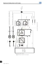
The overload current is given as a function of the speed being applied to the motor, according to the overload
curve. The parameter P0156, P0157 and P0158 are the three points used to form the motor overload curve, as
presented in the
.
% Rated Speed
% P0401
P0156
0 5 50 100
110
105
100
98
90
65
0
P0157
Curve for a motor with separated ventilation
Curve for a Self-ventilated motor
P0158
Figure 15.2:
Overload protection levels
With the setting of the overload current curve, it is possible to set an overload value that varies according to the
operation speed of the motor (factory setting), improving the protection for self-ventilated motors, or a constant
overload level for any speed applied to the motor (motors with separated ventilation).
This curve is adjusted automatically when P0406 (Motor Ventilation) is set during the “Oriented Start-up” routine
(refer to this parameter description in the
).
Summary of Contents for CFW700
Page 2: ......
Page 4: ......
Page 8: ...Summary...
Page 34: ...2 General Information 2 4 CFW700...
Page 38: ...3 About the CFW700 3 4 CFW700...
Page 56: ...7 Starting up and Settings 7 4 CFW700...
Page 58: ...8 Available Control Types 8 2 CFW700...
Page 78: ...10 VVW Control 10 8 CFW700...
Page 158: ...13 Digital and Analog Inputs and Outputs 13 28 CFW700...


