


Digital and Analog Inputs and Outputs
13
CFW700 | 13-1
13 DIGITAL AND ANALOG INPUTS AND OUTPUTS
This section presents the parameters for the configuration of the CFW700 inputs and outputs, as well as the
parameters for the command of the inverter in the Local or Remote Situations.
13.1 I/O CONFIGURATION
13.1.1 Analog Inputs
Two analog inputs (AI1 and AI2) are available in the CFW700 standard configuration.
With those inputs it is possible, for instance, the use of an external speed reference or the connection of a sensor for
the temperature measurement (PTC). The details for those configurations are described in the following parameters.
P0018 – AI1 Value
P0019 – AI2 Value
Adjustable
Range:
-100.00 to 100.00 %
Factory
Setting:
Properties:
ro
Access groups
via HMI:
READ or I/O
Description:
These read only parameters indicate the value of the analog inputs AI1 and AI2, as a percentage of the full scale.
The indicated values are the ones obtained after the offset action and the multiplication by the gain. Refer to the
description of the parameters P0230 to P0240.
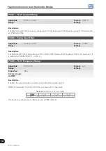
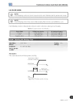
P0230 – Analog Input Dead Zone
Adjustable
Range:
0 = Inactive
1 = Active
Factory
Setting:
0
Properties:
Access groups
via HMI:
I/O
Description:
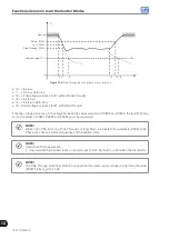
This parameter acts only for the analog inputs (AIx) programmed as speed reference, and it defines if the Dead
Zone at those inputs is Active (1) or Inactive (0).
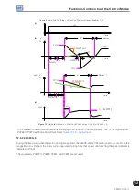
If the parameter is configured as Inactive (P0230=0), the signal at the analog input will work on the Speed
Reference starting from the minimum value (0 V / 0 mA / 4 mA or 10 V / 20 mA), and will be directly related to
the minimum speed programmed at P0133. Refer to the
.
Summary of Contents for CFW700
Page 2: ......
Page 4: ......
Page 8: ...Summary...
Page 34: ...2 General Information 2 4 CFW700...
Page 38: ...3 About the CFW700 3 4 CFW700...
Page 56: ...7 Starting up and Settings 7 4 CFW700...
Page 58: ...8 Available Control Types 8 2 CFW700...
Page 78: ...10 VVW Control 10 8 CFW700...
Page 158: ...13 Digital and Analog Inputs and Outputs 13 28 CFW700...


