Applications
19
CFW700 | 19-17
The Accelerate input is active when 24 V is applied and inactive when 0 V is applied. Otherwise, the Decelerate
input is active when 0 V is applied and inactive when 24 V is applied.
Parameter P1011 shows the current value of the speed reference in rpm and it helps to keep the speed reference
value when there is no accelerate or decelerate command.
Parameter P1012 sets if the speed reference backup is enabled or if it will go to 0 rpm in a new inverter enabling.
19.3.2 Operation
Before making a detailed description of the parameters related to this application, a step by step guide for showing
the operation of the electronic potentiometer application is presented next.
NOTE!
For the proper implementation of the electronic potentiometer application (EP), it is essential to check
if the inverter is properly configured to run the motor at the desired speed. Thus, check the following
settings:
Torque boosts (P0136 and P0137) and slip compensation (P0138) if in V/f control mode.
Run the auto tuning if in vector mode.
Acceleration and deceleration ramps (P0100 to P0103) and current limiting (P0135 for V/f and
VVW control, or P0169/P0170 for vector control).
Setting up the Electronic Potentiometer Application
1. Selecting the application:
When the electronic potentiometer application is enabled, setting P1003 = 2, the default applicative is loaded
in the SoftPLC function, making it available for use in the CFW700.
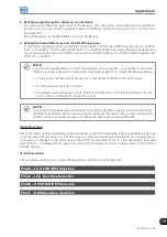
2. Setting the digital input for the Accelerate command:
It is necessary to define which digital input will do the Accelerate command of the electronic
potentiometer application. In order to do that, one of the DI parameters selection (P0263 to P0270) should
be set to 20 = Function 1 of the Application.
Recommendation: set the DI3 (P0265 = 20) to do the Accelerate command.
3. Setting the digital input for the Decelerate command:
It is necessary to define which digital input will do the Decelerate command of the electronic
potentiometer application. In order to do that, one of the DI parameters selection (P0263 to P0270) should
be set to 21 = Function 2 of the Application.
Recommendation: set the DI4 (P0266 = 21) to do the Decelerate command.
4. Setting the speed reference source:
In case the electronic potentiometer application should operate in local mode, P0221 must be set to 7 = SoftPLC.
When the electronic potentiometer application should operate in remote mode, P0222 must be set to 7 = SoftPLC.
5. Setting the reference backup:
Determine if the value of the speed reference will be hold (P1012 = 1) or not (P1012 = 0) in case of a new
energization of the inverter.
6. Speed References Limits:
Set P0133 and P0134, according to the application.
Summary of Contents for CFW700
Page 2: ......
Page 4: ......
Page 8: ...Summary...
Page 34: ...2 General Information 2 4 CFW700...
Page 38: ...3 About the CFW700 3 4 CFW700...
Page 56: ...7 Starting up and Settings 7 4 CFW700...
Page 58: ...8 Available Control Types 8 2 CFW700...
Page 78: ...10 VVW Control 10 8 CFW700...
Page 158: ...13 Digital and Analog Inputs and Outputs 13 28 CFW700...


