2 Technical Description
2.6 Technical Data
Manual
38
SIPART DR21
C73000-B7476-C143-08
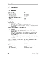
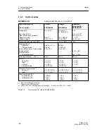
Service life
mechanical
230 V AC 8A electrical ohmic
2
¢
10
7
switching cycles
10
5
switching cycles
Spark quenching element
Series circuit 22 nF/220
Ω
parallel to it
varistor 420 V
rms
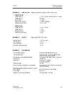
Digital outputs DO1 to DO2 (with wired-or diodes)
Signal status 0
≤
1.5 V
Signal status 1
+19 V to 26 V
load current
≤
30 mA
Short-circuit current
≤
50 mA
Static destruction limit
-1 V to +35 V
Measuring transmitter feed L+
Rated voltage
+20 to 26 V
load current
≤
60 mA, short-circuit-proof
Short-circuit current
≤
200 mA clocking
Static destruction limit
--1 to +35 V
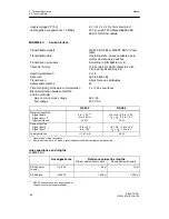
CPU data
Cycle time
100 ms
Minimum integration speed
dy
dt
kp
⋅
xd
tn
0.1
⋅
0.1 %
10
4
s
=
=
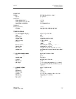
A/D conversion except UNI module
6DR2800-8V
Procedure
Successive approximation per input > 120
conversions and averaging within 20 or
16.67 ms
Modulation range
-5 % to 105 % of the modulation range
Resolution
11 bits
≙
0.06 %
of the modulation range
Zero error
≤
0.2 % of the modulation range
Full scale error
≤
0.2 % of the modulation range
Linearity error
≤
0.2 % of the modulation range
Temperature influence
Zero point
≤
0.05 %/10 K of the modulation range
Full scale
≤
0.1 %/10 K of the modulation range
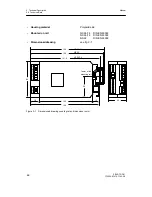
Setpoint- and manipulated variable
adjustment
Setting
With 2 keys (more - - less)
Speed
progressive
Resolution
wi
y
1 digit
0.1 % of rated range 0 to 20 mA
Summary of Contents for SIPART DR21
Page 1: ...SIPART DR21 C73000 B7476 C143 08 1 SIPART DR21 6DR 210 Edition 08 2010 Manual ...
Page 2: ...SIPART DR21 C73000 B7476 C143 08 2 ...
Page 148: ...4 Installation 4 2 Electrical Connection Manual 148 SIPART DR21 C73000 B7476 C143 08 ...
Page 180: ...5 Operation 5 5 CPU self diagnostics Manual 180 SIPART DR21 C73000 B7476 C143 08 ...
Page 242: ...Manual 242 SIPART DR21 C73000 B7476 C143 07 ...


