5 Operation
5.4 Configuration modes
Manual
SIPART DR21
C73000-B7476-C143-08
157
D
Conditions for adaptation
- The controller must be in a stationary condition, i.e. the controlled variable x must be
constant.
- The system to be adapted must be a system with compensation, i.e. the manipulated
variable step in the adaptation must lead to a constant controlled variable x.
- No adaptation can be performed in stepper controllers with S2 = 2 and firmware version
A04 or earlier. Adaptation here is only possible in connection with the external feedback
(jumper setting via S19 to y
R
). As of firmware A05 or higher the change in the manipu-
lated variable required for adaptation is determined from the drive runtime. Accurate set-
ting of the parameters tP and tM is presumed.
- It is recommended to start the adaptation from the y value (operating point) usual for this
type of control circuit.
D
Pre adaptation
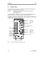
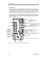
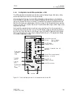
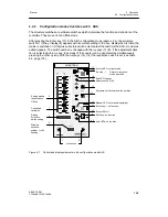
The controller must be switched to manual (key (11)) before entering the selection mode.
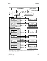
The ”AdAP” menu can only be selected at S48 > 0. It is called with the Enter key (11). The
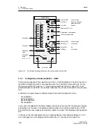
adaption LED (19) is off and indicates readiness for adaptation. First the parameters for the
presettings (tU, dPv, dY) are displayed. They must be set according to the desired step com-
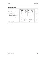
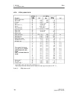
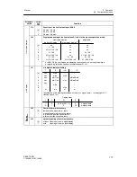
mand. Then the old online parameters appear on the displays (see table 5-1, page 155) with
their respective value. This can only be preset in the onPA mode.
NOTICE
Make sure the set step command causes no damage to the process control
system. The control loop is not closed during the adaptation. The adaptation
procedure is unsuitable for systems without compensation (systems with inte-
gral behaviour).
The selection of the parameters is made with the keys (7), (8), the setting of the values with
the keys (14), (15). The LED (13) flashes when ”Strt” appears in the w/x display (3). Adapta-
tion can now be started with Enter (11).
D
During adaptation
The adaptation LED (19) flashes indicating that the adaptation is in progress. The process
can be monitored over the whole process display. Keys (7), (8), (14) and (15) have no func-
tion. The w/x display (3) can be switched over with the key (6) depending on the position of
S81. The adaptation can be aborted manually with the key (16).
D
Aborted adaptation
The current adaptation can be aborted manually or automatically by the error monitor.
The adaptation LED (19) is off indicating readiness for adaptation after error acknowledge-
ment. The Enter LED (13) flashes as a request for error acknowledgement.
Manual abortion can be activated in the event of danger by pressing the Exit key (16). The
program then jumps to the selection mode after AdAP. From there you can return to the pro-
cess operation level by pressing the Exit key (16) again. The controller is in manual oper-
ation and the manual manipulated variable can be adjusted.
Summary of Contents for SIPART DR21
Page 1: ...SIPART DR21 C73000 B7476 C143 08 1 SIPART DR21 6DR 210 Edition 08 2010 Manual ...
Page 2: ...SIPART DR21 C73000 B7476 C143 08 2 ...
Page 148: ...4 Installation 4 2 Electrical Connection Manual 148 SIPART DR21 C73000 B7476 C143 08 ...
Page 180: ...5 Operation 5 5 CPU self diagnostics Manual 180 SIPART DR21 C73000 B7476 C143 08 ...
Page 242: ...Manual 242 SIPART DR21 C73000 B7476 C143 07 ...

