4 Installation
4.2 Electrical Connection
Manual
SIPART DR21
C73000-B7476-C143-08
135
D
6DR2800-8V
(universal module for analog input)
The universal module can only be inserted in slot 1. It is assigned to AI3 with S6> 3 and
structured with S8, S9, S10.
The measuring ranges are set with the menu CAE3 (see chapter 5.4.6, page 173).
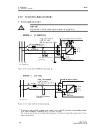
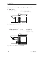
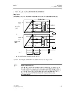
- Connector pin assignment for mV-transmitter S8 = 0
Direct input U
max
=
±
175 mV
R
L4
R
L1
R
L1
+R
L4
≤
1 k
Ω
+
--
mV
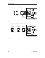
Block diagram mV-module 6DR2800-8V
i
m
U
+REF
+
--
A
D
Sensor
6DR2800-8V
4
3
2
1
Figure 4-19 Connection UNI-module AE3 S8=0
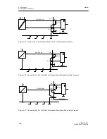
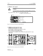
- Pin assignment measuring range plug 6DR2805-8J for U or I S8 = 0
4
3
2
1
89k1
200R
8k95
50R
1k
10 V
+
--
SMART
20 mA
+
--
perm. common mode
voltage 50 V UC
U
H
+
--
Measuring range plug 6DR2805-8J
Block diagram mV-module 6DR2800-8V
i
m
U
+REF
+
--
A
D
Sensor
6DR2800-8V
4
3
2
1
+
--
10 V
20 mA
4L
20 mA
2L
SMART
--
L+
GND
1)
DR21: Jumper must be plugged
1)
--
Figure 4-20 Connection UNI-module AE3 S8=0 with measuring range plug
Summary of Contents for SIPART DR21
Page 1: ...SIPART DR21 C73000 B7476 C143 08 1 SIPART DR21 6DR 210 Edition 08 2010 Manual ...
Page 2: ...SIPART DR21 C73000 B7476 C143 08 2 ...
Page 148: ...4 Installation 4 2 Electrical Connection Manual 148 SIPART DR21 C73000 B7476 C143 08 ...
Page 180: ...5 Operation 5 5 CPU self diagnostics Manual 180 SIPART DR21 C73000 B7476 C143 08 ...
Page 242: ...Manual 242 SIPART DR21 C73000 B7476 C143 07 ...

