4 Installation
4.2 Electrical Connection
Manual
SIPART DR21
C73000-B7476-C143-08
143
D
6DR2801-8D
2DO relay 35 V
!
WARNING
The relay contacts are only permitted for switching voltages up to UC 35 C.
DO3 and DO4 in slot 3 (S22 = 2)
Set function with S58 to S68
Set direction of effect with S69 to S75
5
497
4
496
6
495
Terminals
Labeling according to DIN 45140
DO4
2x
68
V
A
C
1
μ
1
μ
22
Ω
3
397
2
396
1
395
DO3
1
μ
1
μ
22
Ω
....
......
AC contact load capacity
U
≤
35 V
I
≤
5 A
max. power
≤
150 VA
DC contact load capacity
U
≤
35 V
I
≤
5 A
max. power
≤
80 W at 35 V
≤
100 W at 24 V
2x
68
V
A
C ....
......
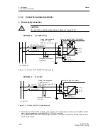
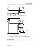
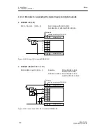
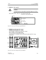
Figure 4-37 Connection of 2DO (relay) -module 6DR2801-8D
D
6DR2804-8A (coupling relay 230 V, 4 relay)
6DR2804-8B (coupling relay 230 V, 2 relay)
Can be snapped onto DIN rail on the back of the controller.
Wired externally to the desired digital outputs.
These must then be structured with S57 to S68.
e.g. connection for
±
Δ
y outputs in the S-controller with coupling relay 230 V, 2 relays
(6DR2804-8B)
420 V
420 V
GND
DO1
+
Δ
y
DO2
--
Δ
y
220
Ω
22n
11/
12
220
Ω
22n
N L
1
2
3
6
4
5
9
7
8
GND
8
7
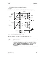
Figure 4-38 Connection of coupling relay 230 V 6DR2804-8B
Summary of Contents for SIPART DR21
Page 1: ...SIPART DR21 C73000 B7476 C143 08 1 SIPART DR21 6DR 210 Edition 08 2010 Manual ...
Page 2: ...SIPART DR21 C73000 B7476 C143 08 2 ...
Page 148: ...4 Installation 4 2 Electrical Connection Manual 148 SIPART DR21 C73000 B7476 C143 08 ...
Page 180: ...5 Operation 5 5 CPU self diagnostics Manual 180 SIPART DR21 C73000 B7476 C143 08 ...
Page 242: ...Manual 242 SIPART DR21 C73000 B7476 C143 07 ...


