3
Functional description of the structure switches
3.6
Controller output structures (S2, S49 to S55)
Manual
SIPART DR21
C73000-B7476-C143-08
103
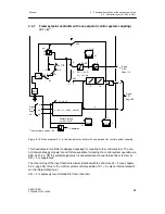
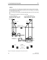
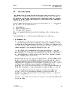
The manual adjustment is made as an incremental adjustment by far overranging of the
three-position switch so that manual adjustment is also possible when the position feedback
is interrupted. (Only at S54=1 or 3)
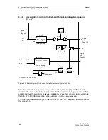
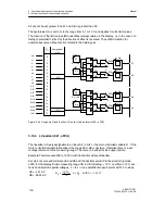
To simplify commissioning of the position control circuit, the manual manipulated variable is
preset absolutely at S54=0 (manipulated variable of the K-controller) so that the setpoint of
the position control circuit is changed continuously by the manual manipulated variable in
this structure switch position to enable optimization (see chapter 6.2, page 183 ). It should
be taken into account here that the manual manipulated variable which is also displayed is
changed faster by the actuating time tY than the active manipulated variable on the actuator
and a lag therefore takes place. The controlling status can be monitored on the
Δ
y-LEDs (9)
in the y-display. After optimization, S54 should be set to 1 to display the active manipulated
variable via the position feedback y
R
.
Summary of Contents for SIPART DR21
Page 1: ...SIPART DR21 C73000 B7476 C143 08 1 SIPART DR21 6DR 210 Edition 08 2010 Manual ...
Page 2: ...SIPART DR21 C73000 B7476 C143 08 2 ...
Page 148: ...4 Installation 4 2 Electrical Connection Manual 148 SIPART DR21 C73000 B7476 C143 08 ...
Page 180: ...5 Operation 5 5 CPU self diagnostics Manual 180 SIPART DR21 C73000 B7476 C143 08 ...
Page 242: ...Manual 242 SIPART DR21 C73000 B7476 C143 07 ...

