2 Technical Description
2.5 Function principle
Manual
28
SIPART DR21
C73000-B7476-C143-08
(AdAP)
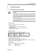
In the
adaptation level
the output conditions for automatic adaptation of the con-
troller parameters to the process is preset and adaptation started.
(CAE3)
The measuring range is set and fine adjustment made if necessary here for the
UNI-module
.
The CAE3-menu is only displayed if it has been released in the structuring level
(structure switch S6>3).
2.5.2
Option module
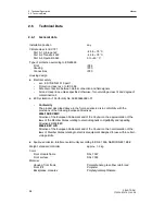
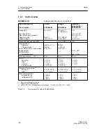
The following option modules are described in this chapter
6DR2800-8J
I/U-module
6DR2800-8R
R-module
6DR2800-8V
UNI-module
6DR2805-8A
reference point
6DR2805-8J
measuring range plug
6DR2801-8D
module with 2 DO (relay)
6DR2801-8E
module with 2 DI and 4 DO
6DR2801-8C
module with 5 DI
6DR2803-8P
serial interface PROFIBUS-DP
6DR2803-8C
serial interface RS 232/RS 485
6DR2804-8A
module with 4 DO relays
6DR2804-8B
module with 2 DO relays
6DR2800-8J
I/U-module
D
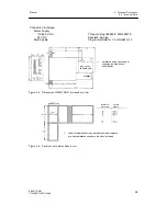
Input variables current 0/4 to 20 mA or voltage 0/0.2 to 1 V or 0/2 to 10 V
The module’s input amplifier is designed as a differentiating amplifier with shuntable gain for
0 to 1 V or 0 to 10 V input signal. For current input signals the 49.9
Ω
0.1 % impedance is
switched on by plug-in bridges on the module. The start value 0 mA or 4 mA or 0 V or 0.2 V
(2 V) is defined by configuration in the standard controller. The differentiating amplifier is de-
signed for common mode voltages up to 10 V and has a high common mode suppression.
As a result it is possible to connect the current inputs in series as for electrical isolation when
they have common ground. For voltage inputs this circuit technique makes it possible to sup-
press the voltage drops on the ground conductor by two-pole wiring on potential-bound volt-
age sources. We refer to an electronic potential isolation.
6DR2800-8R
R-module
D
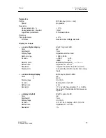
Input for resistance- or current potentiometer
Potentiometers with rated values of 80
Ω
to 1200
Ω
can be connected as resistance trans-
mitters. A constant current of Is = 5 mA is fed to the potentiometer wiper. The wiper resis-
tance is therefore not included in the measurement. Resistors are switched parallel to the
potentiometer by settings on the module and a rough range selection made. Start of scale
and -- full scale are set with the two adjusting pots on the back of the module.
Summary of Contents for SIPART DR21
Page 1: ...SIPART DR21 C73000 B7476 C143 08 1 SIPART DR21 6DR 210 Edition 08 2010 Manual ...
Page 2: ...SIPART DR21 C73000 B7476 C143 08 2 ...
Page 148: ...4 Installation 4 2 Electrical Connection Manual 148 SIPART DR21 C73000 B7476 C143 08 ...
Page 180: ...5 Operation 5 5 CPU self diagnostics Manual 180 SIPART DR21 C73000 B7476 C143 08 ...
Page 242: ...Manual 242 SIPART DR21 C73000 B7476 C143 07 ...


