6 Commissioning
6.3 Adaptation of the S-controller to the actuating drive
Manual
184
SIPART DR21
C73000-B7476-C143-08
The minimum possible resolution is transferred with the system gain Ks to the controlled
variable
Δ
x = K
s
·
Δ
y
The parameter tA (minimum turn-off duration) should be chosen at least great enough that
the actuating drive is safely disconnected under consideration of the power switches con-
nected before it before a new pulse appears (especially in the opposite direction). The
greater the value of tA, the more resistant to wear the switching- and drive elements con-
nected after the controller operate and the greater the dead time of the controller under
some circumstances. The value of tA is usually set identical to the value of tE.
tA = tE = 120 to 240 ms are recommended for 60 s actuating drives. The more restless the
controlled system, the greater the two parameters should be selected if this is reasonably
justified by the controller result.
The response threshold AH must be set corresponding to the set tE and the resulting
Δ
y or
Δ
x. The following condition must be satisfied:
AH >
Δ
x
2
or AH >
Ks
⋅
tE
⋅
100 %
2
⋅
tP (or tM)
Otherwise the controller outputs positioning increments although the control deviation has
reached the smallest possible value due to the finite resolution. For setting AH, see chapter
5.4, page 154.
D
S-controller with external feedback (S2 = 3)
The position control circuit is optimized with the online-parameters tP/tM. The same relation-
ships apply as in the S-controller with internal position feedback whereby the dynamic of the
position control circuit (non-linearities, follow-up) is added to the criteria of the processability
of the positioning increments by the final control element. It will usually be necessary to se-
lect tP/tM and the resulting response threshold smaller than in the S-controller with internal
position feedback for the above mentioned reasons.
The position control circuit is optimized in manual mode. To do this, S54 is set to 0 for the
optimizing phase so that the manual manipulated variable is preset as an absolute value. It
must be noted that the active manipulated variable trails the manipulated variable display
due to the actuating time of the actuator.
In the case of non-linearity in the position control circuit, the optimization must take place in
the range of greatest slope.
Procedure for optimization of the position control circuit:
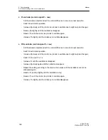
- Set S54 to 0 (position controller also active in manual mode)
- Set tA and tE so that the actuating drive can
just
process the positioning increments (see
S-controller with internal feedback).
- Set 1st order filter of the y
R
-input (t1, 2, 3 or 4) to 0.01 TP/TM (real actuating time of the
drive).
- Increase tP/tM until the position control circuit overshoots due to small manual changes
in the manipulated variable (observe opposite pulse on the
Δ
y-LEDs (10) in the y-dis-
play).
Summary of Contents for SIPART DR21
Page 1: ...SIPART DR21 C73000 B7476 C143 08 1 SIPART DR21 6DR 210 Edition 08 2010 Manual ...
Page 2: ...SIPART DR21 C73000 B7476 C143 08 2 ...
Page 148: ...4 Installation 4 2 Electrical Connection Manual 148 SIPART DR21 C73000 B7476 C143 08 ...
Page 180: ...5 Operation 5 5 CPU self diagnostics Manual 180 SIPART DR21 C73000 B7476 C143 08 ...
Page 242: ...Manual 242 SIPART DR21 C73000 B7476 C143 07 ...


