2 Technical Description
2.3 Features
Manual
SIPART DR21
C73000-B7476-C143-08
23
D
Others
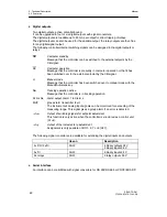
Further functions are also possible. Examples:
Meaning
see chapter
Adaptation-
procedure
Automatic determining of the controller parameters by
means of a robust adaptation method which also consider-
ably simplifies commissioning of even critical controlled sys-
tems.
Configuring level
AdAP; 3.9 (page
113) and 5.4.3 (page
156)
adaptive filter for
xd
Filter which dampens amplitude-dependent interference, the
value of the dampening is adapted automatically.
onPA-Parameter tF
3.10.1 (pg. 115) and
5.4.2 (page 155)
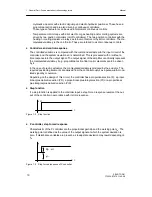
Setpoint ramp
Prevents the setpoint or nominal ratio being changed too
fast. The desired adjustment speed can be set. The time for
the change is set from 0 to 100 % here. The setpoint ramp is
not active at x-tracking and digital signal tS .
oFPA-Parameter tS;
3.4.1 (pg. 55) and
5.4.4 (pg. 163)
Filter for all inputs
A 1st order filter can be connected to every analog input.
onPA-Parameters t1
to t4; 3.2 (pg. 47)
and 5.4.2 (pg. 155)
Root extractor for
all controller inputs
A root extractor can be connected before every analog input. Structure switches
S11 to S14; 3.2 (pg.
47) and 5.4.5 (pg.
165)
Linearizer for an
input variable
A linearizer with 13 (equidistant) support points and para-
bolic approximation can be assigned to one of the analog
inputs AI1 to AI4 or to the controlled variable x1.
Structure switch
S21; 3.10.4 (pg.
118) and 5.4.5 (pg.
165)
Initialization of the
display x/w
The controlled variable x and the command variable w can
be displayed in physical values.
oFPA-Parameter dA,
dE; 3.4.1 (pg. 55)
and 5.4.4 (pg. 163)
Limits for the set-
point w
The setpoint can be limited anywhere within the selected
measuring range.
oFPA-Parameter
SA, SE;
3.4.1 (pg. 55) and
5.4.4 (pg. 163)
Limits of the
manipulated
variable y
The manipulated variable y can be limited within the setting
range –10% and +110 %.
(Not in S-controllers with internal feedback)
onPA-Parameter YA,
YE; 3.5 (pg. 91) and
5.4.2 (pg. 155)
x-Tracking
The setpoint w is tracked to the controlled variable x in
manual-, tracking- and DDC-operation as well as at the
safety setpoint.
Structure switch
S43; 3.4.1 (pg. 55)
and 5.4.5 (pg. 165)
Limit value alarms
Any controller-internal variables or inputs can be monitored
for limit values. The output is by way of alarms A1 to A4.
Structure switches
S76 and S77; 3.10.3
(pg. 117) and 5.4.5
(pg 165)
Transmitter
monitoring
All or specific analog inputs can be monitored for dropping
below- or- exceeding the range. In the event of a fault, the
four-digit digital display outputs a message selectively for
every input. A system fault can be output via the digital out-
put MUF.
Structure switches
S4 to S7, S66; 3.2
(pg. 47) and 5.4.5
(pg. 165)
Adaptation of the
direction of action
SIPART DR21 operates with normal direction in the factory
setting. The direction of the controller can be changed for
reversing systems.
Structure switch
S46; 3.5 (pg 91) and
5.4.5 (pg. 165)
Restart conditions
After mains recovery the controller starts automatically with
the structured operating modes, setpoints and manipulated
variables.
Structure switch
S82; 3.10.5 (pg.120)
and 5.4.5 (pg. 165)
Summary of Contents for SIPART DR21
Page 1: ...SIPART DR21 C73000 B7476 C143 08 1 SIPART DR21 6DR 210 Edition 08 2010 Manual ...
Page 2: ...SIPART DR21 C73000 B7476 C143 08 2 ...
Page 148: ...4 Installation 4 2 Electrical Connection Manual 148 SIPART DR21 C73000 B7476 C143 08 ...
Page 180: ...5 Operation 5 5 CPU self diagnostics Manual 180 SIPART DR21 C73000 B7476 C143 08 ...
Page 242: ...Manual 242 SIPART DR21 C73000 B7476 C143 07 ...


