3
Functional description of the structure switches
3.3
Digital input signal processing (S23 to S41)
Manual
SIPART DR21
C73000-B7476-C143-08
53
0/2 (3/4)
1)
S51
4
0/1
CB
DI
0,1,2,3
S51
2/3/(4/5)
1)
S51
3/4
0/1/2
S51
3/4
0/1/2
2/3 (4/5)
1)
S85
0,1
0,1
2/3 (4/5)
1)
0/1
S85
S41
3/5
1)
S85
CB
0
2
S42
0/1
2/3 (4/5)
1)
S85
0,2
S41
1
1
He
ES
≥
&
&
&
Si
ES
≥
S51
ge
0,1(3/4)
1)
2
tSH
ES
≥
Si
bLb
bLS
bLPS
P
N
tS
PAU
+yBL
-yBL
tSH 3)
0/1
0
1
≥
&
2/3 (4/5)
1)
S85
0/1
≥
2/3 (4/5)
1)
S85
0/1
H
SES
Si
DI
bLb
DI
bLS
DI
bLPS
DI
P
DI
N
DI
tS
DI
+yBL
DI
-yBL
DI
tSH
DI
3)
He
DI
CB
ES
RC=Int
∧
CB
not for S1 = 4
Control
unit/process-
display
&
≥
0/1/2/4
1)
1
1
0
S
≥
RB = Int
--1
1)
as of software version --A5
2)
as of software version --B3
3)
as of software version --B5
4)
as of software version --C1
&
bLb
ES
2)
Int
ES
S85
2
1
0
C gn
gn
1
1
S84
0/1
4)
3
2
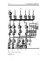
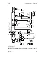
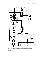
Figure 3-3 Linking the digital inputs DI1 to DI7 with the control signals via the SES (S41, S42, S51, S85)
Summary of Contents for SIPART DR21
Page 1: ...SIPART DR21 C73000 B7476 C143 08 1 SIPART DR21 6DR 210 Edition 08 2010 Manual ...
Page 2: ...SIPART DR21 C73000 B7476 C143 08 2 ...
Page 148: ...4 Installation 4 2 Electrical Connection Manual 148 SIPART DR21 C73000 B7476 C143 08 ...
Page 180: ...5 Operation 5 5 CPU self diagnostics Manual 180 SIPART DR21 C73000 B7476 C143 08 ...
Page 242: ...Manual 242 SIPART DR21 C73000 B7476 C143 07 ...

