6 Commissioning
6.4 Setting the filter and the response threshold
Manual
SIPART DR21
C73000-B7476-C143-08
185
- Reduce tP/tM slightly again until the position control circuit settles.
- Reset S54 to 1 (position controller no longer active in manual mode)
6.4
Setting the filter and the response threshold
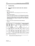
Set the structure switch S3 to the mains frequency 50 or 60 Hz existing in the system (factory
setting 50 Hz) to suppress faults due to the mains frequency.
D
Filter of first order of analog inputs
The filter time constants (t1 to t4) for the input filters are set in the onPA-parameterization
mode and to the greatest possible value permitted by the control circuit without affecting the
controllability (t1 to t4 < Tg). When using the adaptation method the appropriate input filters
must be optimized.
D
Adaptive, non-linear filters of the control difference
Since the dead zone sets itself automatically and its size is therefore unknown, the time tF
(onPA) can only be selected so great that the control circuit cannot oscillate in the case of a
large dead zone (tF less than Tg). When using the D-part (PD, PID) the use of the adaptive,
non-linear filter is strongly recommended because the input noise amplified by Kp·vv can be
suppressed.
If filters are required, they must be set before using the adaptation method.
D
Optimization of the response threshold AH
If the output of the controller is to additionally settled or the load on the actuator reduced, the
necessary response threshold AH can be increased. The response threshold AH is given in
three-position controllers (S2 = 2, 3) by the setting of tE (see chapter 6.3, page 183) and
must automatically be greater than zero. In K-controllers and two-position controllers
(S2 = 0, 1) a response threshold of approx. 0.5 % is recommendable.
It must be taken into account that the remaining control error can assume the value of the
set response threshold.
Summary of Contents for SIPART DR21
Page 1: ...SIPART DR21 C73000 B7476 C143 08 1 SIPART DR21 6DR 210 Edition 08 2010 Manual ...
Page 2: ...SIPART DR21 C73000 B7476 C143 08 2 ...
Page 148: ...4 Installation 4 2 Electrical Connection Manual 148 SIPART DR21 C73000 B7476 C143 08 ...
Page 180: ...5 Operation 5 5 CPU self diagnostics Manual 180 SIPART DR21 C73000 B7476 C143 08 ...
Page 242: ...Manual 242 SIPART DR21 C73000 B7476 C143 07 ...

