3 Functional description of the structure switches
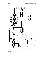
3.4 Controller types (S1, S42 to S45)
Manual
72
SIPART DR21
C73000-B7476-C143-08
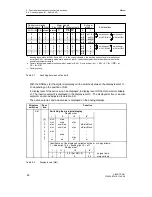
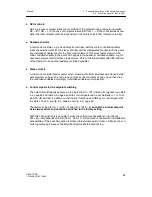
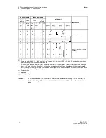
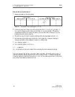
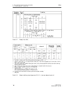
Notes to table 3-9 and table 3-7
1)
Manual operation can be achieved by:
Control signals
Message signals
Digital input He
Front Hi
Front Manual LED
Digital output H
0
1
0
1
0
0
1
1
0
0,9
6)
1
1
0
1
1
1
Table 3-8
Generation of the control signal H = Hi
∨
He
2)
In DDC-operation the setting current is switched off at S52 = 1. Source for y
E
at S85 = 0,
1,(4, 5 as of software version --A05), y is
N
. At S85 = 2, 3, y acts
ES
(SES). The external
manipulated variable fed in through the SES (y
ES
) is tracked. When feeding in via y
N
the
feeding instrument must be tracked.
3)
The table is shown for static computer switching without acknowledgement, S41 = 0.
4)
By OR-linking of the digital output H with the control signal Si no computer standby or
computer operation can be signaled in manual -- or safety mode.
5)
0.5 = Flashing rhythm 1 : 1
6)
0.9 = Flashing rhythm 0.1 off, 0.9 on
(
↗
)
= adjustable
(n) = is followed up to the value active before switching, therefore bumpless switching
The control signal Track (N) has no function in DDC-controllers. The tables apply for S45 = 0
(with tracking of the inactive setpoint to the active setpoint). At S45 = 1 (without tracking) and
x-tracking, automatic operation starts with wi = x (xd = 0), the active setpoint runs to the old set
value wi via the possibly set setpoint ramp tS.
Summary of Contents for SIPART DR21
Page 1: ...SIPART DR21 C73000 B7476 C143 08 1 SIPART DR21 6DR 210 Edition 08 2010 Manual ...
Page 2: ...SIPART DR21 C73000 B7476 C143 08 2 ...
Page 148: ...4 Installation 4 2 Electrical Connection Manual 148 SIPART DR21 C73000 B7476 C143 08 ...
Page 180: ...5 Operation 5 5 CPU self diagnostics Manual 180 SIPART DR21 C73000 B7476 C143 08 ...
Page 242: ...Manual 242 SIPART DR21 C73000 B7476 C143 07 ...


