3
Functional description of the structure switches
3.4 Controller types (S1, S42 to S45)
Manual
SIPART DR21
C73000-B7476-C143-08
57
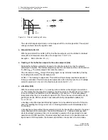
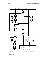
x-tracking only takes full effect if the tracking of the inactive setpoint is locked onto the active
setpoint (S45 = 0) so that not only the active setpoint w but also the setpoint source which is
supplying after switching to automatic operation is tracked.
At S45 = 1 (without tracking) the control difference during the A-operation is 0 but the old,
untracked setpoint becomes effective again after switching to automatic operation. With the
setpoint ramp tS this step-shaped setpoint change takes place via a time ramp.
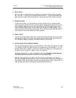
This combination is always useful when it is not guaranteed during A-operation (especially
in safety mode) that the actual value will be driven to the desired rated value by the actuat-
ing manipulation and the tracking variable would not be correct in full x-tracking.
D
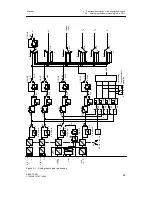
Constants c1 to c7
Linking of the process variables with the constants is possible depending on the controller
type, whereby the constants c1 to c3 are used for the control variable links, the constants c4
and c5 for the command variable links.
The constants are set in the parameterization mode onPA.
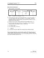
The constant c6 serves for proportioning the disturbance variable connection z to the con-
troller output ya (see figure 3-7, page 62). It can be set in the parameterization mode onPA.
The constant c7 is used in P-controller operation as a factor for increasing the Kp-value.
(P/PI-switchover, see figure 3-21, page 92).
D
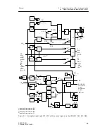
Control signals for the setpoint switching
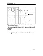
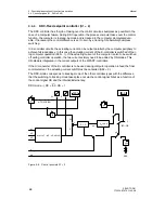
If available in the single controller types, the setpoint switching takes place depending on the
control signals Int (Internal/External key) and CB (Computer standby) as an AND-function
RC = Int
∧
CB and its negation. The status of the control signal CB and the Internal key (16)
is indicated by the C LED (18) and the Internal LED (17).
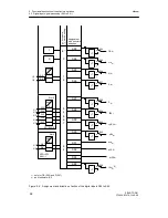
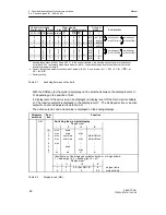
With S42 the Internal/External key (16) can be set out of function and can block in the posi-
tions Internal or External (see figure 3-3, page 53 ). The factory setting is S42 = 0 (only In-
ternal).
With S23, the CB-signal can be set to Low or High or assigned to a digital input, (see fig-
ure 3-2, page 52). The factory setting is S23 = 8, CB = High.
The setpoint switching can be varied freely with these structuring possibilities.
Summary of Contents for SIPART DR21
Page 1: ...SIPART DR21 C73000 B7476 C143 08 1 SIPART DR21 6DR 210 Edition 08 2010 Manual ...
Page 2: ...SIPART DR21 C73000 B7476 C143 08 2 ...
Page 148: ...4 Installation 4 2 Electrical Connection Manual 148 SIPART DR21 C73000 B7476 C143 08 ...
Page 180: ...5 Operation 5 5 CPU self diagnostics Manual 180 SIPART DR21 C73000 B7476 C143 08 ...
Page 242: ...Manual 242 SIPART DR21 C73000 B7476 C143 07 ...

