3 Functional description of the structure switches
3.6 Controller output structures (S2, S49 to S55)
Manual
108
SIPART DR21
C73000-B7476-C143-08
D
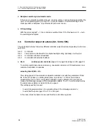
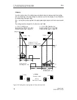
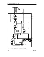
Direction-dependent blocking operation
Blocking operation is controlled by the control signals
±
yBL. All other control signals have
no function. If a control signal is applied the manipulated variable output is blocked direction-
dependently, i.e. only changes in the opposite direction are allowed. If both control signals
are applied simultaneously, the output is blocked absolutely. The direction-dependent block-
ing is necessary especially in S-controllers with internal feedback and actuators with limit
stop switches to avoid integral saturation. If the control circuit is opened on reaching the end
position of the actuator, further integration of the controller must be prevented in order to be
able to react immediately in the event of control difference reversal.
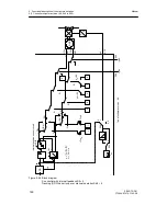
As described above, the control signals
±
yBL have priority over Si and H or N. Priority of H
or N can be selected via S49. All these operating modes have priority over automatic oper-
ation.
Signaling of the switching states is made by the LEDs Manual (12) and y-external (13).
When manual mode is active or preselected (if the priority opeating modes are active), the
manual LED lights up. He = 1 is signaled by a flashing rhythm of 0.9 (control signal) if Hi =
0 (i.e. is in automatic mode by the manual/automatic switching). When switching the control
signal He from 1
!
0 the automatic mode becomes active.
Tracking-(DDC), safety-and blocking operation is signaled by the y-External LED. Flashing
rhythm 0.5 indicates that in ”manual operation priority over tracking operation”, manual oper-
ation is active but tracking operation is prepared and after switching to automatic operation
also becomes active.
D
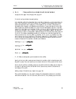
Blocking of the manual/automatic switching (S51)
With S51 the manual/automatic switching can be blocked in the operating mode Automatic
mode only or Manual mode only. The other operating modes are still possible. Then, tracking
mode is only possible if tracking has priority over manual mode (see figure 3-22, page 96).
D
Manual mode in the case of a transmitter fault (S50)
With S50 manual mode can be switched to when the transmitter group fault message occurs
(see chapter 3.2, page 47). Manual operation starts at S50=1 with the last y or at S50 = 2
with the parameterized YS. In both cases the manual manipulated variable can be adjusted
with the
±
Δ
y keys after switching.
D
Source and direction of effect of the y-display (S54, S55)
With S54 the y-display is switched to the different display sources or switched off. The abso-
lute manipulated variable y or the split range-manipulated variables y
1
and y
2
in two-position
controllers heating/cooling or the position feedback-signal y
R
in three-position-S-controllers
can be displayed.
With S55 the display direction rising/falling can be selected (see chapter 6.1), page 181.
Summary of Contents for SIPART DR21
Page 1: ...SIPART DR21 C73000 B7476 C143 08 1 SIPART DR21 6DR 210 Edition 08 2010 Manual ...
Page 2: ...SIPART DR21 C73000 B7476 C143 08 2 ...
Page 148: ...4 Installation 4 2 Electrical Connection Manual 148 SIPART DR21 C73000 B7476 C143 08 ...
Page 180: ...5 Operation 5 5 CPU self diagnostics Manual 180 SIPART DR21 C73000 B7476 C143 08 ...
Page 242: ...Manual 242 SIPART DR21 C73000 B7476 C143 07 ...

