3
Functional description of the structure switches
3.5 Control algorithm
Manual
SIPART DR21
C73000-B7476-C143-08
93
D
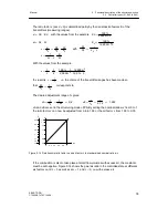
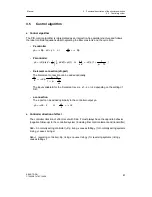
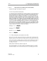
Operating point yo for P-controllers
The operating point yo of the P-controller can be set either automatically or as a parameter
(onPA).
Automatic working point (Yo = Auto)
Whenever there is no automatic operation (manual-, tracking-, safety- or blocking operation)
the operating point yo is tracked so that switching to automatic operation is bumpless.
This gives an automatic setting of the operating point yo in manual mode:
yo = y
H
- (Kp · c7 · (w - x
H
) + c6 · z)
If the actual value in manual mode (x
H
) is driven to the desired setpoint w by the appropriate
manual manipulated variable y
H
, the operating point yo is identical to the manual manipu-
lated variable y
H
.
yo = yH or yo = yH + c6 · z.
Fixed working point (Yo = 0 to 100 %)
The controller operates in all operating modes with the working point set as a permanent
parameter.
D
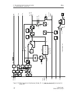
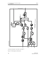
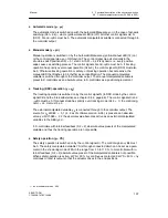
manipulated variable limit YA, YE
The manipulated variable limit with the parameters YA and YE is only active in automatic
operation or in all operating modes depending on the switch position of S53. The limits of
these parameters are at -10 and +110 %. However, it should be taken into account that the
controller neither outputs negative actuating currents nor detects any negative position feed-
back signals.
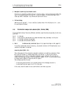
If the manipulated variable y
a
reaches one of the limits YA or YE in the limited operating
mode, further integration is aborted to avoid integral saturation. This ensures that the
manipulated variable can be changed immediately after reversing the polarity.
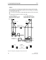
In manual-, tracking-(DDC) or safety operation, the manipulated variable y at S53 = 0 (limit-
ing only in automatic operation) can be driven out of the limiting range. When switching to
automatic operation the last manipulated variable is then transferred bumplessly but only
changes in the manipulated variable in the direction of the YA to YE range are subsequently
executed.
The manipulated variable limiting is possible at K-, two-position-and three-position-stepper-
controllers with external position feedback (S2 = 0, 1, 3).
Summary of Contents for SIPART DR21
Page 1: ...SIPART DR21 C73000 B7476 C143 08 1 SIPART DR21 6DR 210 Edition 08 2010 Manual ...
Page 2: ...SIPART DR21 C73000 B7476 C143 08 2 ...
Page 148: ...4 Installation 4 2 Electrical Connection Manual 148 SIPART DR21 C73000 B7476 C143 08 ...
Page 180: ...5 Operation 5 5 CPU self diagnostics Manual 180 SIPART DR21 C73000 B7476 C143 08 ...
Page 242: ...Manual 242 SIPART DR21 C73000 B7476 C143 07 ...

