3 Functional description of the structure switches
3.2 Analog input signal processing (S3 to S21)
Manual
48
SIPART DR21
C73000-B7476-C143-08
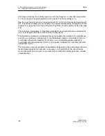
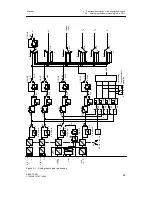
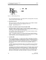
After range monitoring, the 4 analog inputs are each fed through a 1st order filter (parameters
t1 to t4 can be set in the parameterization mode onPA). The factory setting is 1 s.
Now the root of every channel can be extracted with S11 to S14 and they can be linearized with
S21. This allows non-linear process variables to be represented physically correctly as well (see
chapter3.10.4 (page 118 for function principle) setting of the 13 vertex values, see fig. 3-35, page
119).
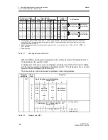
The controllers-, manipulated- or disturbance variables to be processed for the controller types
(S1) can be acquired with S15 to S20 from the 4 analog inputs.
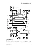
The disturbance variable z is connected either by the D-element or directly to the controller out-
put (S47). y
N
serves as a tracking input for the manipulated variable in K-controllers (S2=0) or
S-controllers with external feedback (S2=3) and y
R
as a manipulated variable feedback in
S-controllers with internal feedback (S2=2) or as a position feedback in S-controllers with exter-
nal feedback (S2=3).
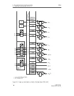
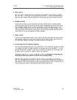
The controllers- or process variables are available for assignment to the analog output (S6) and
the limit value signal (S76 to S80) and can be read in via the SES. With this input structure
most control tasks can be solved in connection with the different controller types and controller
output structures.
Summary of Contents for SIPART DR21
Page 1: ...SIPART DR21 C73000 B7476 C143 08 1 SIPART DR21 6DR 210 Edition 08 2010 Manual ...
Page 2: ...SIPART DR21 C73000 B7476 C143 08 2 ...
Page 148: ...4 Installation 4 2 Electrical Connection Manual 148 SIPART DR21 C73000 B7476 C143 08 ...
Page 180: ...5 Operation 5 5 CPU self diagnostics Manual 180 SIPART DR21 C73000 B7476 C143 08 ...
Page 242: ...Manual 242 SIPART DR21 C73000 B7476 C143 07 ...

