3 Functional description of the structure switches
3.6 Controller output structures (S2, S49 to S55)
Manual
102
SIPART DR21
C73000-B7476-C143-08
D
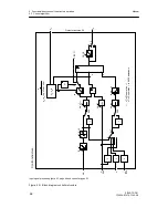
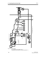
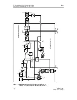
S2 = 3: Three-position step controller (S) with external feedback
see figure 3-27, page 104 and figure 3-28, page 105
To control I-acting motorized actuating drives.
In S-controllers with external feedback the ”internal position control circuit” is replaced by a
real position controller (with the K-controller output y as a setpoint and the position feedback
y
R
as an actual value). As a result a manipulated variable limiting of ya and an absolute
value preset of y
E
and ys are now possible.
With the absolute value preset of y
E
it is also possible to preset the manual manipulated
variable via the SES as an absolute value y
ES
in tracking operation.
Here too the response threshold of the position controller is preset with the parameters tE
(minimum turn-on duration) and tA (minimum turn-off duration) in connection with tP and tM
(actuating time positive/negative direction) which are all set in the parameterization mode
onPA:
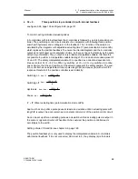
- Switching on
A
ee
= 4
100 %
⋅
tE
tY
- Switching off
A
ea
= 3
100 %
⋅
tE
tY
- Hysteresis
A
ee
-- A
ea
=
100 %
⋅
tE
tY
- Pause
A
a
=
100 %
⋅
tA
tY
tY = tP, tM set actuating time (parameterization mode onPA)
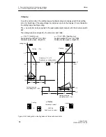
If a control deviation of xds
≥
Aee is set up, the three-position switch switches direction-
dependently to continuous contact. xds is reduced by the negative follow-up of the position
control circuit until xds
<
Aea is reached. The continuous contact is now switched off.
After the pause time tA pulses of length tE are output with subsequent pause time tA until
xds
≤
Aee is reached.
-Aea -Aee
Aea Aee
-
Δ
y
+
Δ
y
xdS
These single pulses are also output if xds coming from zero does not reach Aee. These
single pulses which are not fully transformed into the path change (rotational movement)
additionally settle the control circuit, i.e. in theory (without lag) the single pulses would switch
off at 0.25 or 0.5 Aee. The opposite direction can only occur at appropriate control deviation
after the pause time tA.
Summary of Contents for SIPART DR21
Page 1: ...SIPART DR21 C73000 B7476 C143 08 1 SIPART DR21 6DR 210 Edition 08 2010 Manual ...
Page 2: ...SIPART DR21 C73000 B7476 C143 08 2 ...
Page 148: ...4 Installation 4 2 Electrical Connection Manual 148 SIPART DR21 C73000 B7476 C143 08 ...
Page 180: ...5 Operation 5 5 CPU self diagnostics Manual 180 SIPART DR21 C73000 B7476 C143 08 ...
Page 242: ...Manual 242 SIPART DR21 C73000 B7476 C143 07 ...

