3
Functional description of the structure switches
3.10 Other functions of the standard controller
Manual
SIPART DR21
C73000-B7476-C143-08
117
3.10.3 Limit value alarm (S76 to S80)
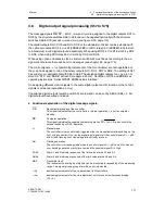
The limit value alarm pairs A1, A2 and A3, A4 are assigned to the controller-internal variables
xd, x ... AI3A, AI4A, lxdl by the structure switches S76 and S77. Every limit value alarm pair can
be set to the monitoring functions Max/Min, Min/Min or Max/Max by S78 (A1, A2) or S79 (A3,
A4).
The response thresholds A1 to A4 and the hysteresis HA are set in the structuring mode oFPA.
According to the switch position of S80 only the display or the display and adjustment of A1 to
A4 is possible in the process operation level. In this case the switching cycle of the Shift key (6)
is extended by the response thresholds A1, A2 or A1 to A4:
Example display order switching key (6): w - y - A1 - A2 - A3 - A4 - x . . .
The respective limit value is displayed on the y-display (9), the value on the x/w-digital display
(3) or the w-bar display (2) and set depending on the assignment physically according to the
display format of the digital x/w-display or in %.
S76
assigned
Display format
Parameter range
S1
S76,
S77
assigned
to
digital x/w-dis-
play S80 > 0
Bar display
S80 = 5, 6
x/w-display
0
1
2
0
#
5/17
xd
#
wv/lxdl
according to
dA to dE
-1999 to 9999
%
-110 % to 110 %
referenced to
dE - dA = 100 %
2
4
5
6
6
#
16
y
#
AI4A
%
%
- 110 % to 110 %
0
#
xd
#
%
%
- 110,0 % to 110,0 %
#
3/17
#
w/lxdl
according to**)
Ad to Ed
-1999 to 9999
%
--110 % to +110 %**)
referenced to
Ad--Ed=100%
3
1/2/3*)
x1/x/w
according to
Ad to Ed
-1999 to 9999
%
--110 % to +110 %
referenced to
Ad--Ed=100%
4
#
5
xv
#
wv
according to
dA to dE
-1999 to 9999
%
-110 % to 110 %
referenced to
dE--dA = 100 %
6
#
16
y
#
AI4A
%
%
- 110 % to 110 %
Table 3-17
Display format of the limit values A1 to A4
*) as of software version --A9
**) as of software version --C1
Summary of Contents for SIPART DR21
Page 1: ...SIPART DR21 C73000 B7476 C143 08 1 SIPART DR21 6DR 210 Edition 08 2010 Manual ...
Page 2: ...SIPART DR21 C73000 B7476 C143 08 2 ...
Page 148: ...4 Installation 4 2 Electrical Connection Manual 148 SIPART DR21 C73000 B7476 C143 08 ...
Page 180: ...5 Operation 5 5 CPU self diagnostics Manual 180 SIPART DR21 C73000 B7476 C143 08 ...
Page 242: ...Manual 242 SIPART DR21 C73000 B7476 C143 07 ...


