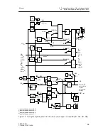
3 Functional description of the structure switches
3.3 Digital input signal processing (S23 to S41)
Manual
54
SIPART DR21
C73000-B7476-C143-08
D
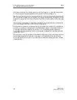
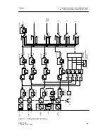
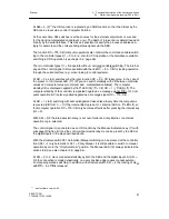
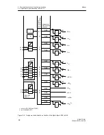
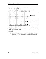
Functional explanation of the control signals
CB
Computer-standby
Depending on the controller type this digital signal together with the
Internal/External key effects either switching in the setpoint range or
DDC-operation begins. Central computer-fail-line in SPC and DDC-operation.
He
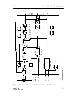
Manual external
This signal blocks the output of the controller and enables direct manual
adjustment of the manipulated variable on the front control panel.
N
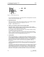
Tracking
With this signal the output of the K-controller and the three-position-stepper
controller with external position feedback is tracked to the tracking signal y
N
.
Si
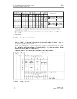
Safety operation
In K-controllers and three-position-stepper controllers with external position
feedback, the manipulated variable adopts the parameterized safety value. In
three-position-stepper controllers with internal feedback the manipulated
variable runs independently of the safety setting value to a defined limit
position.
bLS
Blocking structuring
The whole configuration is blocked with the exception of the online
parameterization level.
bLPS
Blocking parameterization and structuring
The entire configuring of the instrument is blocked, this means the
parameterization as well. Only the normal process operation according to the
preselected controller type is permitted.
bLb
Blocking operation
This signal blocks the entire front panel operation of the instrument.
P
P-Operation controller
With this signal the controller is switched to P-operation.
tS
setpoint ramp
The set setpoint ramp time can be made ineffective with this signal
(tS = High
≙
ramp switched off).
tSH
setpoint hold (setpoint ramp
)
The setpoint change is stopped with this signal. The setpoint change continues
when the signal is reset.
yBL
Direction-dependent blocking of the manipulated variable
Direction-dependent limiting of the manipulated variable by external signals,
e.g. from the limit switches of the actuating drives. This limiting is effective in
every operating mode.
Summary of Contents for SIPART DR21
Page 1: ...SIPART DR21 C73000 B7476 C143 08 1 SIPART DR21 6DR 210 Edition 08 2010 Manual ...
Page 2: ...SIPART DR21 C73000 B7476 C143 08 2 ...
Page 148: ...4 Installation 4 2 Electrical Connection Manual 148 SIPART DR21 C73000 B7476 C143 08 ...
Page 180: ...5 Operation 5 5 CPU self diagnostics Manual 180 SIPART DR21 C73000 B7476 C143 08 ...
Page 242: ...Manual 242 SIPART DR21 C73000 B7476 C143 07 ...

