3
Functional description of the structure switches
3.4 Controller types (S1, S42 to S45)
Manual
SIPART DR21
C73000-B7476-C143-08
75
3.4.5
Controlled ratio controller (S1 = 3)
w
V
ES
x
w
wv
x2
wv
x1
x2
w
VEA
v
is
=
x1 - c5
x2
y
a
W
+
-
X
P I D
ya+c6
·
z
y
y
H
z
0000
w=v
·
x2+c5
tS
wvi
SES
00
v = vA to vE
v = wv
·
(vE - vA)+vA
xv
x1
w
Int
∧
CB
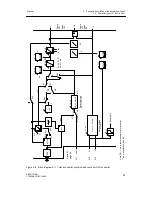
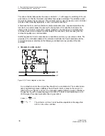
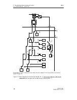
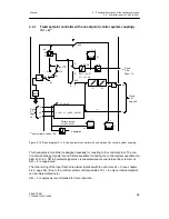
Figure 3-11 Control principle S1 = 3
In a ratio control the commanding process variable x2 is weighted with the adjustable ratio
factor and a basic value c5 added if necessary. The result forms the setpoint w for the following
controlled process variable x1.
w = v · x2 + c5
With
xd = w - x1
the result is
xd = v · x2 + c5 - x1
In the controlled state (xd = 0) the result is
v =
x1 -- c5
x2
, i.e. in the controlled state and at
c5 = 0
x1
x2
behaves according to the set ratio factor v.
A typical application are combustion rules where a fuel volume x1 belongs to every air volume
x2 to guarantee optimum combustion.
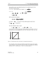
The ratio factor range v = vA to vE is determined with the parameters vA and vE in the structur-
ing mode oFPA in the range from 0.0 to 9.999 (factory setting vA = 0, vE = 1). In addition a
basic value c5 (parameterization mode onPA) can be connected in the range from --1.999 to
9.999 (factory setting = 0.0).
The standardized nominal ratio wv (wvi or wv
E
) in the range from 0 to 1 is converted to the ratio
factor range.
v = wv (vE - vA) + vA
With w = v · x2 + c5 the result is w = [wv (vE - vA) + vA] x2 + c5
In the ratio controller the standardized nominal ratio wv and the standardized actual ratio xv are
displayed on the digital x/w-displays respectively in display levels I and II. A physical display is
possible with dA, dE, dP. The controlled variable x1 and the evaluated commanding process
variable w are displayed on the analog x - and w-displays respectively so that a direct control
Summary of Contents for SIPART DR21
Page 1: ...SIPART DR21 C73000 B7476 C143 08 1 SIPART DR21 6DR 210 Edition 08 2010 Manual ...
Page 2: ...SIPART DR21 C73000 B7476 C143 08 2 ...
Page 148: ...4 Installation 4 2 Electrical Connection Manual 148 SIPART DR21 C73000 B7476 C143 08 ...
Page 180: ...5 Operation 5 5 CPU self diagnostics Manual 180 SIPART DR21 C73000 B7476 C143 08 ...
Page 242: ...Manual 242 SIPART DR21 C73000 B7476 C143 07 ...


