3
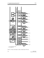
Functional description of the structure switches
3.3
Digital input signal processing (S23 to S41)
Manual
SIPART DR21
C73000-B7476-C143-08
51
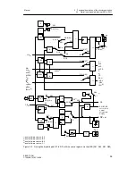
At S85 = 3, (5)
1)
the OR-function is replaced by an AND-function so that the CB set by the
SES can be reset via a central Computer Fail line.
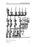
At the same time, S85 switches over the sources for the external setpoint w
ES
or w
EA
and
for the tracking manipulated variable y
ES
or y
N
. The depth of intervention is determined addi-
tionally by the serial interface. This makes it possible to specify the process variables ana-
logly for example and the corresponding status signals via the SES.
The function RC = Int
∧
CB (computer operation) also controls the command variable switch-
ing in the controller types S1 = 0 to 4, i.e. also in SPC-operation or the disturbance variable
switching in DDC-operation (see chapter 3.4, page 55).
The two controller types S1 = 5/6 operate without command variable switching. The Internal
key and the control signal CB are available with the link RC = Int
∨
CB for locking operation
through the serial interface (e. g. when linking to control systems).
At S41 = 0 a static switchover by the logic function RC = Int
∧
CB takes place. In the case of
the preset to Int (Internal LED (17) off) you can switch statically with CB between controller
values and computer values (command- and manipulated variables). The computer
standby CB is displayed negated by the C-LED (18) (C = CB, CB = 1
≙
C LED off). The
computer standby of the controller is signaled negated as a message signal RB = Int. Com-
puter operation RC is also signalled negated as a message signal RC = Int
∧
CB .
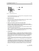
At S41 = 1 static switching with acknowledgement takes place. Every time the computer is
recovered (CB from 0
!
1) If the internal flip-flop is set to 1 (internal LED on, C LED off), so
that computer operation RC = Int
∧
CB only becomes effective after pressing the internal key
(Int = 0).
With S42 = 0/2 the internal/external key is set out of order and only internal- or external
operation is pre-selected.
The control signal H is generated as an OR-function by the Manual-/Automatic key (11) with
subsequent flip-flop (Hi) and the control signal He whereby He can be preset by the SES or
the digital inputs in the way described above.
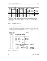
With the structure switch S51 Automatic-/Manual switching can be blocked at the controller
front (S51 =1 only Automatic or S51 = 2 only Manual. It is still possible to switch to manual
operation by He in the ”Only Automatic” position. The Manual LED (12) always indicates the
active status (see also chapter 3.6, page 94).
At S51 = 0 to 2, He is connected statically by both the SES and the digital inputs. At S51 =
3/4 the connection is made dynamically, i.e. every positive edge causes manual-automa-
tic-manual operation switching. In addition, with structure switch S51 = 4 the locking of He
ES
with RC = Int
∨
CB is released.
1)
as of software version --A5
Summary of Contents for SIPART DR21
Page 1: ...SIPART DR21 C73000 B7476 C143 08 1 SIPART DR21 6DR 210 Edition 08 2010 Manual ...
Page 2: ...SIPART DR21 C73000 B7476 C143 08 2 ...
Page 148: ...4 Installation 4 2 Electrical Connection Manual 148 SIPART DR21 C73000 B7476 C143 08 ...
Page 180: ...5 Operation 5 5 CPU self diagnostics Manual 180 SIPART DR21 C73000 B7476 C143 08 ...
Page 242: ...Manual 242 SIPART DR21 C73000 B7476 C143 07 ...


