3
Functional description of the structure switches
3.6
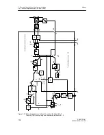
Controller output structures (S2, S49 to S55)
Manual
SIPART DR21
C73000-B7476-C143-08
107
D
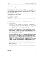
Automatic mode (y = y
a
)
The automatic mode is switched on with the Automatic/Manual key or in the case of dynamic
switching (S51= 3,4)
1)
via He (yellow manual LED (8) off). All other control signals He, N
(DDC), Si and
±
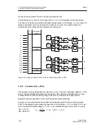
yBL must be 0. The automatic manipulated variable is connected through to
the controller output.
D
Manual mode (y = y
H
)
Manual operation is switched on by the Automatic/Manual key (yellow manual LED(12) on)
or the control signal He as an OR function. The control signal He acts statically in the
structure switch positions S51 = 0,1 static. At S51 = 3,4 it is dynamic, i.e. every positive
edge causes a switching process. The control signals Si and
±
yBL must be 0. If tracking
operation has priority over manual operation (S49=0), the control signal N (DDC) must also
be 0. Otherwise tracking operation or safety- or blocking operation become active, the
manual-LED then flashes in 0.5 rhythm as an identification. The manual manipulated
variable is switched through to the controller output. The manual manipulated variable is
preset in K-controllers as an absolute value, in S-controllers as a positioning increment.
D
Tracking-(DDC)-operation (y = y
E
)
The tracking operation is switched on by the control signal N (in DDC-mode by the control
signal CB and the Internal/External, see chapter 3.4.4, page 68). The control signals Si and
±
yBL must be 0. If manual mode has priority over tracking mode (S49 = 1) the control sig-
nal H = Hi
∨
He must be 0.
The external manipulated variable y
E
is connected through to the controller output. The
source for y
E
at S85 = 0, 1,(4, 5 as of software version --A05), is preset as an absolute
value y
N
. With S85 = 2, 3 the absolute value becomes active as an external manipulated
variable via the SES (y
ES
).
In S-controllers with internal feedback (S2 = 2), absolute value presets of the manipulated
variable and thus the tracking operation are not possible.
D
Safety operation (y = YS)
The safety operation is switched on by the control signal Si. The control signal
±
yBL must
be 0. The safety manipulated variable YS is through connected which can be set as a para-
meter in the structuring mode oFPA in the range from -10 to 110 %. In S-controllers with in-
ternal feedback (S2 = 2) absolute value preset of the manipulated variable is not possible.
When safety operation is active, at YS
≤
50 % -
Δ
y continuous contact and at YS > 50 % +
Δ
y
continous contact is output so that the actuator drives to the end positions.
1)
as of software version - A05
Summary of Contents for SIPART DR21
Page 1: ...SIPART DR21 C73000 B7476 C143 08 1 SIPART DR21 6DR 210 Edition 08 2010 Manual ...
Page 2: ...SIPART DR21 C73000 B7476 C143 08 2 ...
Page 148: ...4 Installation 4 2 Electrical Connection Manual 148 SIPART DR21 C73000 B7476 C143 08 ...
Page 180: ...5 Operation 5 5 CPU self diagnostics Manual 180 SIPART DR21 C73000 B7476 C143 08 ...
Page 242: ...Manual 242 SIPART DR21 C73000 B7476 C143 07 ...


