3
Functional description of the structure switches
3.4 Controller types (S1, S42 to S45)
Manual
SIPART DR21
C73000-B7476-C143-08
83
D
Control units
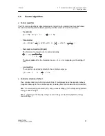
The integrated control unit function always includes a setpoint generator and a manual
control station in the following versions:
-- trackable K-setpoint generator
-- S-setpoint generator
-- trackable K-manual control station (S2 = 0)
-- S-two-position control unit with 2 outputs (heating/cooling) (S2 = 1)
-- S-three-position manual control unit internal feedback (S2 =2)
-- S-three-position manual control unit external feedback (S2 =3)
The ability to combine setpoint generator- and manual control station type depends on the
application. Either the setpoint generator or the manual control station can use the K-output,
the remaining function must have an S-output.
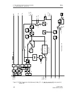
- Setpoint generator
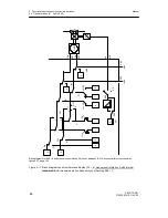
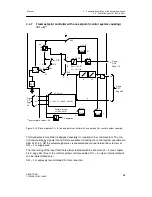
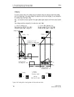
see figure 3-16, page 82
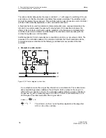
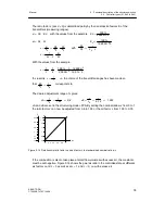
S- and K-setpoint generators are installed parallel. In the S-setpoint generator, the
switching outputs
±
Δ
w can be locked depending on the Internal key (16) and the control
signal CB, the status message is output by the signal lamps Int and C, see table 3-7,
page 71. The feedback of the setpoint adjusted incrementally by the switching outputs
takes place via the w-display (input w
EA
, the switching is blocked in position Ext, S42 =
1).
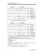
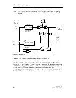
In the K-setpoint generator the tracking of the internal setpoint is controlled dependent on
the Internal key (16) and the control signal CB, see table 3-7, page71. The tracking vari-
able is fed in via w
EA
. The active setpoint is output by assignment of w to the analog out-
put AO (S56 = 2/3).
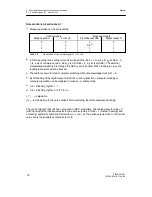
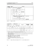
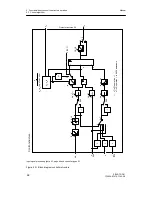
With the Shift key (6) the digital x/w-display can be switched between the display levels
I
to
IV
depending on the position of S81. The controlled variable is displayed in the display
level
I
. In display level
II
the active w can be displayed, in display level
III
the controlled
variable x1. The inactive setpoint is displayed in the display level
IV
. The displayed active
or external setpoint can also be adjusted (see table 3-11, page 84).
The active setpoint- and actual value is displayed on the analog displays.
Summary of Contents for SIPART DR21
Page 1: ...SIPART DR21 C73000 B7476 C143 08 1 SIPART DR21 6DR 210 Edition 08 2010 Manual ...
Page 2: ...SIPART DR21 C73000 B7476 C143 08 2 ...
Page 148: ...4 Installation 4 2 Electrical Connection Manual 148 SIPART DR21 C73000 B7476 C143 08 ...
Page 180: ...5 Operation 5 5 CPU self diagnostics Manual 180 SIPART DR21 C73000 B7476 C143 08 ...
Page 242: ...Manual 242 SIPART DR21 C73000 B7476 C143 07 ...


