6 Commissioning
6.1 Adapting the direction of control action to the controlled system
Manual
SIPART DR21
C73000-B7476-C143-08
181
6
Commissioning
6.1
Adapting the direction of control action to the controlled
system
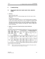
D
Definitions
Normal control action system
Rising y causes rising x; e.g. an increasing energy supply or mass flow causes a rising
temperature.
Normal effecting actuator (valve):
Increasing current or positioning c
y cause the actuating element (increasing y)
to open, e.g. more energy or greater mass flow. y
displ.
is the displayed manipulated variable.
The direction of control action is referred to the controlled variable x1. The following state-
ments apply for transmitters with normal control action (increasing physical variable causes
increasing transmitter current), increasing process display (dE
>
dA) and no falling charac-
teristic in the linearizers.
D
Direction of control action of system and final control element known
K-controller
The following is prescribed:
Select the desired control action here:
This gives the settings of S46
Direc-
tion of
control
Direc-
tion of
control
Direc-
tion of
control
20 mA
pressing the right key
causes in manual operation
This gives the settings of S46
and S55 and the mode of oper-
ation of the controller
control
action
of the
system
control
action
of the
actuator
control
action
of the
system
and the
actuator
20 mA
on
actuat-
ing cur-
rent ly
valve
Actual
value/
con-
trolled
variable
S46
Kp
(cP)
S55
y
displ.
=
l
normal
normal
100 %
rises
opens
rises
0
pos.
0
y
normal
revers-
ing
revers-
ing
0 %
falls
opens
rises
1
neg.
1
100 % -y
normal
revers-
0 %
falls
closes
rises
1
neg.
1
100 % -y
revers-
i
normal
revers-
ing
100 %
rises
opens
falls
1
neg.
0
y
revers
ing
revers-
i
normal
100 %
rises
closes
rises
0
pos.
0
y
ing
0 %
falls
opens
falls
0
pos.
1
100 % -y
Two more lines could be added to the table which are useless in practice: normal action system in which the actual values
falls with a rising change in the manipulated variable.
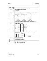
Table 6-1
Direction of control action and y-display direction of control action of the system- and final
control element direction of control action in K-controllers
Summary of Contents for SIPART DR21
Page 1: ...SIPART DR21 C73000 B7476 C143 08 1 SIPART DR21 6DR 210 Edition 08 2010 Manual ...
Page 2: ...SIPART DR21 C73000 B7476 C143 08 2 ...
Page 148: ...4 Installation 4 2 Electrical Connection Manual 148 SIPART DR21 C73000 B7476 C143 08 ...
Page 180: ...5 Operation 5 5 CPU self diagnostics Manual 180 SIPART DR21 C73000 B7476 C143 08 ...
Page 242: ...Manual 242 SIPART DR21 C73000 B7476 C143 07 ...


