4 Installation
4.1 Mechanical Installation
Manual
SIPART DR21
C73000-B7476-C143-08
121
4
Installation
4.1
Mechanical Installation
D
Selecting the Installation Site
Maintain an ambient temperature of 0 to 50
_
C. Don’t forget to allow for other heat sources
in the vicinity. Remember that if instruments are stacked on top of each other with little or no
gap between them, additional heat will be generated. The front and rear of the controller
should have good accessibility.
4.1.1
Work prior to installation
The controller type 6DR2100-5 is set to 230 V AC mains voltage in the as-delivered state. The
switching contacts are locked. The backplane module must be removed to change the mains
voltage setting or to unlock the relay contacts.
D
Removing the backplane module
!
CAUTION
The backplane module may only be removed when the mains plug and the
3-pin
±
Δ
y-plug have been removed!
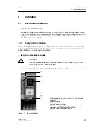
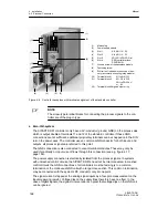
Loosen the fastening screw (6) and pull the module out from the back.
(1)
(2)
(7)
(4)
(5)
(6)
(3)
1 Rating plate (example with two labels 115 V~) (as-delivered
state 230 V~)
2 Plug
y-outputs
3 Mains plug
4 Fastening screw for DIN rail
5 DIN rail 35 mm (DIN EN 50022) for mounting the coupling
relay-modules 6DR2804-8A and 6DR2804-8B
6 Fastening screw for backplane module
7 PE conductor connecting screw
Figure 4-1
Rear of controller
Summary of Contents for SIPART DR21
Page 1: ...SIPART DR21 C73000 B7476 C143 08 1 SIPART DR21 6DR 210 Edition 08 2010 Manual ...
Page 2: ...SIPART DR21 C73000 B7476 C143 08 2 ...
Page 148: ...4 Installation 4 2 Electrical Connection Manual 148 SIPART DR21 C73000 B7476 C143 08 ...
Page 180: ...5 Operation 5 5 CPU self diagnostics Manual 180 SIPART DR21 C73000 B7476 C143 08 ...
Page 242: ...Manual 242 SIPART DR21 C73000 B7476 C143 07 ...

