3
Functional description of the structure switches
3.4 Controller types (S1, S42 to S45)
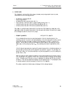
Manual
SIPART DR21
C73000-B7476-C143-08
85
D
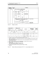
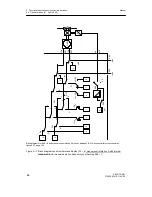
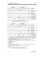
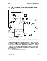
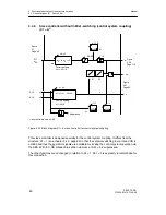
Manual control station (S2 = 0, 1, 2, 3)
see figure 3-17, page 86 and figure 3-18, page 87
The controller output structures which can be configured by S2 are used for the manual con-
trol station function whereby automatic operation is replaced by the ”Hold manipulated vari-
able” mode. All other operating modes are identical with the controller functions. The last
manipulated variable before switching to this operating mode is transferred to this hold oper-
ation and the
Δ
y-keys are inactive. If, in this operating mode, the manipulated variable
output is to be tracked e.g. in 2-wait operation, the tracking operation must be activated by
the control signal N and the input yN.
If only manual control function without switching is desired, the instrument must be blocked
in manual mode with S51 = 2.
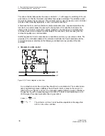
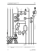
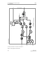
The following figures only show 2 examples. For the other variations, see the block diagrams
of the controller-output structures (fig. 3-22, page 96, figure 3-23, page 97 and figure 3-25,
page 100 to figure 3-28, page 105).
Summary of Contents for SIPART DR21
Page 1: ...SIPART DR21 C73000 B7476 C143 08 1 SIPART DR21 6DR 210 Edition 08 2010 Manual ...
Page 2: ...SIPART DR21 C73000 B7476 C143 08 2 ...
Page 148: ...4 Installation 4 2 Electrical Connection Manual 148 SIPART DR21 C73000 B7476 C143 08 ...
Page 180: ...5 Operation 5 5 CPU self diagnostics Manual 180 SIPART DR21 C73000 B7476 C143 08 ...
Page 242: ...Manual 242 SIPART DR21 C73000 B7476 C143 07 ...


