4 Installation
4.1 Mechanical Installation
Manual
124
SIPART DR21
C73000-B7476-C143-08
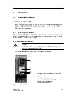
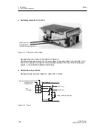
Procedure / removing the front module
- Remove the mains module and any modules which may be plugged in.
- Turn the controller so that you are looking at the operating- and display front module from
the front.
- Carefully lever out the tag plate cover with a screwdriver at the cutout at the top and snap
the cover out of the bottom hinge points by bending slightly. Loosen the screw (captive)
Tilt the top of the front module at the head of the screw and pull it out angled slightly for-
wards.
- The scales can now be removed from the narrow side of the operating- and display front
module with a pair of tweezers.
4.1.2
Installing the controller
D
Panel mounting
The SIPART DR21 controllers are installed either in single panel cutouts or in open tiers (di-
mensions, see figure 2-6, page 35).
Procedure:
- If necessary: Push the self-adhesive sealing ring for sealing the front frame/front panel
over the tube and stick to the back of the tube collar.
(to be ordered separately)
- Insert the controller into the panel cut-out or open tier from the front and fit the two
clamps provided to the controller unit from the rear so that they snap into the cut-outs in
the housing.
- Align the controller and do not tighten the locking screws too tight. The tightening range is
0 to 40 mm.
* Installation depth necessary for
changing the main circuit board
and modules
Relay module
Figure 4-6 Dimensions SIPART DR21, dimensions in mm
Summary of Contents for SIPART DR21
Page 1: ...SIPART DR21 C73000 B7476 C143 08 1 SIPART DR21 6DR 210 Edition 08 2010 Manual ...
Page 2: ...SIPART DR21 C73000 B7476 C143 08 2 ...
Page 148: ...4 Installation 4 2 Electrical Connection Manual 148 SIPART DR21 C73000 B7476 C143 08 ...
Page 180: ...5 Operation 5 5 CPU self diagnostics Manual 180 SIPART DR21 C73000 B7476 C143 08 ...
Page 242: ...Manual 242 SIPART DR21 C73000 B7476 C143 07 ...


