3 Functional description of the structure switches
3.6 Controller output structures (S2, S49 to S55)
Manual
96
SIPART DR21
C73000-B7476-C143-08
N/
DDC
tE
,tP
tA
,tM
S5
1
S5
4
2
1
S8
5
Y1
Y2
+
yBL
-y
BL
oFF
2/
3
2
0/
1/
(4/
5
1)
1
1
1
0
0
0
S5
5
S5
2
N
Si
yn
A
ya
tP
,t
M
(S2
=
0)
YA YE
H
YS
-
Δ
y
S5
7
S5
3
1
0
YA YE
3
0
1
S2
+
Δ
y
S5
7
1
0
S5
3
S2
9
S3
0
S1
9
PI
D
0/
(3/
4)
1)
<>
S1
8
SE
S
0/
1
2/
3/
4/
5
1)
S8
5
tP
,tM
1)
as
of
sof
tw
ar
e
ver
si
on
–A
5
2)
as
of
sof
tw
ar
e
ver
si
on
--B
2
N
/DDC
y
R
y
N
y
H
y
H
A=
H
∧
N
∧
Si
H=
H
i
∨
He
y
H
y
ES
y
HE
S
00
y
An
y
ES
y
S5
6
12/
13
10/
11
0/
1
S5
6
Y1
Y2
2)
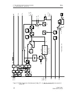
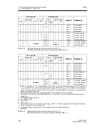
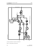
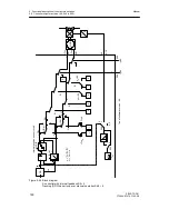
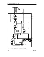
Figure 3-22 Block diagram K-controller S2 = 0 or two-position output S2 = 1
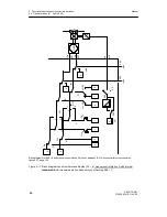
Tracking (DDC) has priority over manual operation S49 = 0
Summary of Contents for SIPART DR21
Page 1: ...SIPART DR21 C73000 B7476 C143 08 1 SIPART DR21 6DR 210 Edition 08 2010 Manual ...
Page 2: ...SIPART DR21 C73000 B7476 C143 08 2 ...
Page 148: ...4 Installation 4 2 Electrical Connection Manual 148 SIPART DR21 C73000 B7476 C143 08 ...
Page 180: ...5 Operation 5 5 CPU self diagnostics Manual 180 SIPART DR21 C73000 B7476 C143 08 ...
Page 242: ...Manual 242 SIPART DR21 C73000 B7476 C143 07 ...

