ISD94100 Series Technical Reference Manual
Sep 9, 2019
Page
747
of 928
Rev1.09
IS
D
9
410
0
S
ER
IE
S
T
E
C
HN
ICA
L
RE
F
E
RE
NCE
M
AN
U
AL
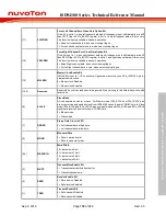
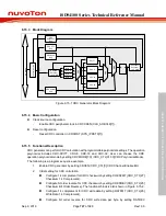
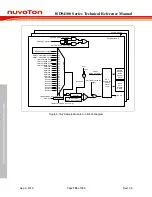
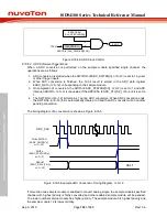
6.15.3 Block Diagram
AHB BUS
MUX
MUX
D
Q
Slave Wrapper
Byte 0
MUX
CCITT
Checksum
Reverse /
1's COMP
CRC-8
CRC-16
CRC-32
CRC CTL
Reg
CRC Seed
Reg
In Data Bit
Reverse /
1's COMP
CRC Control
Unit
Byte 1
Byte 2
Byte 3
CRC
Checksum
Reg
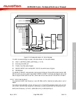
Figure 6.15-1 CRC Generator Block Diagram
6.15.4 Basic Configuration
Clock source configuration
–
Enable CRC peripheral clock in CRCCKEN (CLK_AHBCLK[7]).
Reset configuration
–
Reset CRC controller in CRCRST (SYS_IPRST0[7]).
6.15.5 Functional Description
CRC generator can perform CRC calculation with programmable polynomial settings. The operation
polynomial includes CRC-CCITT, CRC-8, CRC-16 and CRC-32; User can choose the CRC
operation polynomial mode by setting CRCMODE[1:0] (CRC_CTL[31:30] CRC Polynomial Mode).
The following is a program sequence example.
1.
Enable CRC generator by setting CRCEN (CRC_CTL[0] CRC Channel Enable Bit).
2.
Initial setting for CRC calculation.
Configure 1’s complement for CRC checksum by setting CHKSFMT (CRC_CTL[27]
Checksum 1’s Complement).
Configure bit order reverse for CRC checksum by setting CHKSREV (CRC_CTL[25]
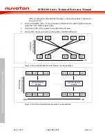
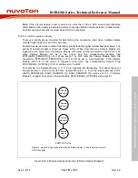
Checksum Bit Order Reverse). The functional block is also shown in Figure 6.15-2.
Configure 1’s complement for CRC write data by setting DATFMT (CRC_CTL[26]
Write Data 1’s Complement).
Configure bit order reverse for CRC write data per byte by setting DATREV


