ISD94100 Series Technical Reference Manual
Sep 9, 2019
Page
652
of 928
Rev1.09
IS
D
9
410
0
S
ER
IE
S
T
E
C
HN
ICA
L
RE
F
E
RE
NCE
M
AN
U
AL
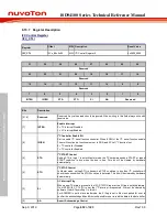
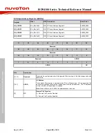
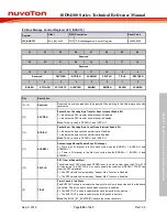
6.13.7 Register Description
I2C Control Register
(I2C_CTL)
Register
Offset
R/W Description
Reset Value
I2C_CTL
0x00
R/W I
2
C Control Register 0
0x0000_0000
31
30
29
28
27
26
25
24
Reserved
23
22
21
20
19
18
17
16
Reserved
15
14
13
12
11
10
9
8
Reserved
7
6
5
4
3
2
1
0
INTEN
I2CEN
STA
STO
SI
AA
Reserved
Bits
Description
[31:8]
Reserved
Reserved. Any values read should be ignored. When writing to this field always write with
reset value.
[7]
INTEN
Enable Interrupt
0 = I
2
C interrupt Disabled.
1 = I
2
C interrupt Enabled.
[6]
I2CEN
I
2
C Controller Enable Bit
Set to enable I
2
C serial function controller. When I2CEN=1 the I
2
C serial function enable.
The multi-function pin function must set to SDA, and SCL of I
2
C function first.
0 = I
2
C controller Disabled.
1 = I
2
C controller Enabled.
[5]
STA
I
2
C START Control
Setting STA to logic 1 to enter Master mode, the I
2
C hardware sends a START or repeat
START condition to bus when the bus is free. This bit will be cleared by hardware
automatically.
[4]
STO
I
2
C STOP Control
In Master mode, setting STO to transmit a STOP condition to bus then I
2
C controller will
check the bus condition if a STOP condition is detected. This bit will be cleared by hardware
automatically.
[3]
SI
I
2
C Interrupt Flag
When a new I
2
C state is present in the I2C_STATUS register, the SI flag is set by hardware.
If bit INTEN (I2C_CTL [7]) is set, the I
2
C interrupt is requested. SI must be cleared by
software. Clear SI by writing 1 to this bit.
For ACKMEN is set in slave read mode, the SI flag is set in 8th clock period for user to
confirm the acknowledge bit and 9th clock period for user to read the data in the data buffer.
[2]
AA
Assert Acknowledge Control

