ISD94100 Series Technical Reference Manual
Sep 9, 2019
Page
691
of 928
Rev1.09
IS
D
9
410
0
S
ER
IE
S
T
E
C
HN
ICA
L
RE
F
E
RE
NCE
M
AN
U
AL
6.14.5.10 Quad I/O Mode
The SPI0 controller also supports Quad I/O transfer when setting the QUADIOEN (SPI0_CTL[22])
to 1. Many general SPI flashes support Quad I/O transfer. The DATDIR bit (SPI0_CTL[20]) is used
to define the direction of the transfer data. When the DATDIR (SPI0_CTL[20]) is set to 1, the
controller will send the data to external device. When the DATDIR (SPI0_CTL[20]) is set to 0, the
controller will read the data from the external device. This function supports 8, 16, 24, and 32 bits
of length.
The Quad I/O mode is not supported when the Slave 3-Wire mode or the Byte Reorder function is
enabled. The DUALIOEN (SPI0_CTL[21]) and QUADIOEN (SPI0_CTL[22]) shall not be set to 1
simultaneously.
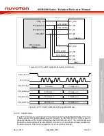
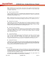
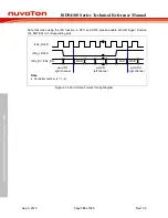
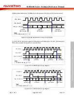
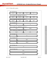
For Quad I/O mode, if both the QUADIOEN (SPI0_CTL[22]) and DATDIR (SPI0_CTL[20]) are set
as 1, the SPI0_MOSI0 and SPI0_MOSI1 are the even bit data output and the SPI0_MISO0 and
SPI0_MISO1 will be set as the odd bit data output. If the QUADIOEN (SPI0_CTL[22]) is set as 1
and DATDIR (SPI0_CTL[20]) is set as 0, all the SPI0_MISO0, SPI0_MISO1, SPI0_MOSI0 and
SPI0_MOSI1 pins will be set as data input ports.
Note:
This function is only supported in SPI0.
SPI0_SS0/1 pin
7 6 5 4 3 2 1 0
SPI0_CLK pin
SPI0_MOSI0 pin
SPI0_MISO0 pin
QUADIOEN
C 8 4 0 C 8 4 0
D 9 5 1 D 9 5 1
C 8 4 0 C 8 4 0
D 9 5 1 D 9 5 1
DATDIR
Master output
Slave input
Master input
Slave output
Output
Output
SPI0_MOSI1 pin
SPI0_MISO1 pin
E A 6 2 E A 6 2
F B 7 3 F B 7 3
E A 6 2 E A 6 2
F B 7 3 F B 7 3
Master output
Slave input
Master input
Slave output
Output
Output
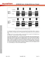
Figure 6.14-20 Bit Sequence of Quad Output Mode

