ISD94100 Series Technical Reference Manual
Sep 9, 2019
Page
481
of 928
Rev1.09
IS
D
9
410
0
S
ER
IE
S
T
E
C
HN
ICA
L
RE
F
E
RE
NCE
M
AN
U
AL
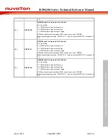
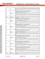
[24]
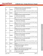
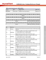
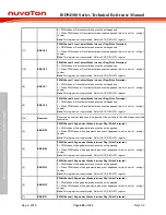
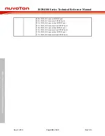
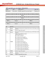
CMPDIEN0
PWM Channel 0 Compare Down Count Interrupt Enable Bits
0 = Compare down count interrupt Disabled.
1 = Compare down count interrupt Enabled.
Note:
In complementary mode, CMPDIEN1, 3, 5 use as another CMPDIEN for channel 0,
2, 4.
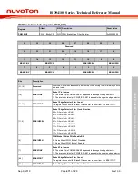
[23:22]
Reserved
Reserved. Any values read should be ignored. When writing to this field always write with
reset value.
[21]
CMPUIEN5
PWM Channel 5 Compare Up Count Interrupt Enable Bits
0 = Compare up count interrupt Disabled.
1 = Compare up count interrupt Enabled.
Note:
In complementary mode, CMPUIEN1, 3, 5 use as another CMPUIEN for channel 0,
2, 4.
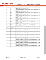
[20]
CMPUIEN4
PWM Channel 4 Compare Up Count Interrupt Enable Bits
0 = Compare up count interrupt Disabled.
1 = Compare up count interrupt Enabled.
Note:
In complementary mode, CMPUIEN1, 3, 5 use as another CMPUIEN for channel 0,
2, 4.
[19]
CMPUIEN3
PWM Channel 3 Compare Up Count Interrupt Enable Bits
0 = Compare up count interrupt Disabled.
1 = Compare up count interrupt Enabled.
Note:
In complementary mode, CMPUIEN1, 3, 5 use as another CMPUIEN for channel 0,
2, 4.
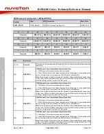
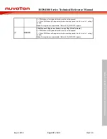
[18]
CMPUIEN2
PWM Channel 2 Compare Up Count Interrupt Enable Bits
0 = Compare up count interrupt Disabled.
1 = Compare up count interrupt Enabled.
Note:
In complementary mode, CMPUIEN1, 3, 5 use as another CMPUIEN for channel 0,
2, 4.
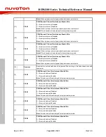
[17]
CMPUIEN1
PWM Channel 1 Compare Up Count Interrupt Enable Bits
0 = Compare up count interrupt Disabled.
1 = Compare up count interrupt Enabled.
Note:
In complementary mode, CMPUIEN1, 3, 5 use as another CMPUIEN for channel 0,
2, 4.
[16]
CMPUIEN0
PWM Channel 0 Compare Up Count Interrupt Enable Bits
0 = Compare up count interrupt Disabled.
1 = Compare up count interrupt Enabled.
Note:
In complementary mode, CMPUIEN1, 3, 5 use as another CMPUIEN for channel 0,
2, 4.
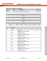
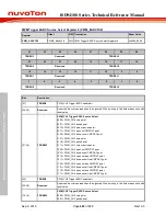
[15:14]
Reserved
Reserved. Any values read should be ignored. When writing to this field always write with
reset value.
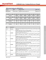
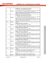
[13]
PIEN5
PWM Channel 5 Period Point Interrupt Enable Bits
0 = Period point interrupt Disabled.
1 = Period point interrupt Enabled.
Note1:
When up-down counter type period point means center point.
Note2:
This channels will read always 0 at complementary mode.
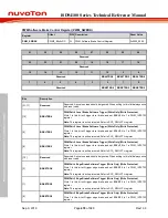
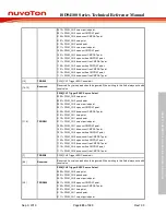
[12]
PIEN4
PWM Channel 4 Period Point Interrupt Enable Bits
0 = Period point interrupt Disabled.
1 = Period point interrupt Enabled.

