ISD94100 Series Technical Reference Manual
Sep 9, 2019
Page
343
of 928
Rev1.09
IS
D
9
410
0
S
ER
IE
S
T
E
C
HN
ICA
L
RE
F
E
RE
NCE
M
AN
U
AL
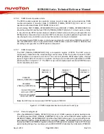
CLKSRC (TIMERx_PWMCLKSRC[2:0])
TMRx_PWMCLK
TMRx_CLK
000
011
100
010
001
TMR0_INT
TMR1_INT
TMR2_INT
TMR3_INT
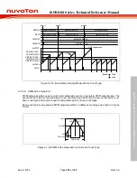
Figure 6.7-5 PWM Counter Clock Source Control
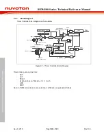
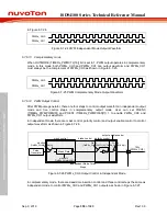
Figure 6.7-6 and Figure 6.7-7 illustrate the architecture of PWM independent mode and
complementary mode. Both independent mode and complementary mode support PWMx_CH0
and PWMx_CH1 output channels in each PWM generator.
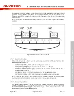
When PWM counter counts to value 0, or PERIOD (TIMERx_PWMPERIOD[15:0]), or CMP
(TIMERx_PWMCMPDAT[15:0]), an event will be generated and trigger the operations following,
such as PWM pulse (Pulse Generator), interrupt signal (Interrupt Generator) and triggering signal
for ADC to start conversion.
Output Control block manages PWM pulse output as well as interrupt events. Dead-Time Control
is available only in PWM complementary mode.
Prescale
Pulse
Generator
Output
Control
TMRx_PWMCLK
Comparator
Counter
a
Interrupt
Generator
Trigger
Generator
NVIC
ADC
Trigger events
Interrupt events
t
i
a
i
t
denotes interrupt events
denotes trigger events
denotes interrupt, trigger and pulse generate events
Note:
TMx
(PWMx_CH0)
i
i
TMx_EXT
(PWMx_CH1)
Figure 6.7-6 PWM Independent Mode Architecture Diagram


