ISD94100 Series Technical Reference Manual
Sep 9, 2019
Page
643
of 928
Rev1.09
IS
D
9
410
0
S
ER
IE
S
T
E
C
HN
ICA
L
RE
F
E
RE
NCE
M
AN
U
AL
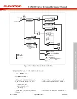
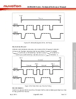
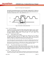
Figure 6.13-24 Setup Time Wrong Adjustment
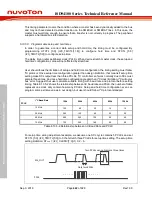
For hold time wrong adjustment example, we use I
2
C Baud Rate = 1200k and PCLK = 72 MHz, the
SCL high/low duty = 60 PCLK. When we set HTCTL [5:0] (I2C_TMCTL[11:6]) to 61 and STCTL
[5:0] (I2C_TMCTL[5:0]) to 0, then SDA output delay will over SCL high duty and cause bus error.
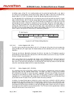
The hold time setting limitation:
HT
limit
= (I2C_CLKDIV[7:0]+1) X 2 - 9.
SCL
SDA
SDA delay over SCL low duty
Bus error
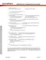
Figure 6.13-25 Hold Time Wrong Adjustment
6.13.5.4 I
2
C Protocol Registers
To control I
2
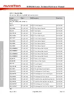
C port through the following fifteen special function registers: I2C_CTL (control
register), I2C_STATUS (status register), I2C_DAT (data register), I2C_ADDRn (address registers,
n=0~3), I2C_ADDRMSKn (address mask registers, n=0~3), I2C_CLKDIV (clock rate register),
I2C_TOCTL (Time-out control register), I2C_WKCTL(wake up control register) and
I2C_WKSTS(wake up status register).
6.13.5.4.1
Address Registers (I2C_ADDR)
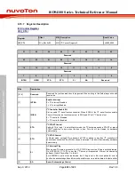
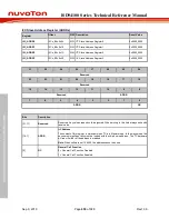
The I
2
C port is equipped with four slave address registers, I2C_ADDRn (n=0~3). The contents of
the register are irrelevant when I
2
C is in Master mode. In Slave mode, the bit field
ADDR(I2C_ADDRn[7:1]) must be loaded with the chip’s own slave address. The I
2
C hardware will
react if the contents of I2C_ADDRn are matched with the received slave address.
The I
2
C ports support the “General Call” function. If the GC bit (I2C_ADDRn [0]) is set the I
2
C port
hardware will respond to General Call address (00H). Clear GC bit to disable general call function.
When the GC bit is set and the I
2
C is in Slave mode, it can receive the general call address by 00H
after Master send general call address to I
2
C bus, then it will follow status of GC mode.
6.13.5.4.2
Slave Address Mask Registers (I2C_ADDRMSK)
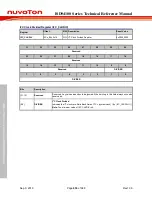
The I
2
C bus controller supports multiple address recognition with four address mask registers
I2C_ADDRMSKn (n=0~3). When the bit in the address mask register is set to 1, it means the
received corresponding address bit is "Don’t care". If the bit is set to 0, it means the received
corresponding register bit should be exactly the same as address register.
6.13.5.4.3
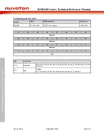
Data Register (I2C_DAT)
This register contains a byte of serial data to be transmitted or a byte which just has been received.
The CPU can be read from or written to the 8-bit (I2C_DAT [7:0]) directly while it is not in the process

