ISD94100 Series Technical Reference Manual
Sep 9, 2019
Page
525
of 928
Rev1.09
IS
D
9
410
0
S
ER
IE
S
T
E
C
HN
ICA
L
RE
F
E
RE
NCE
M
AN
U
AL
6.9 Watchdog Timer (WDT)
6.9.1
Overview
The purpose of Watchdog Timer (WDT) is to perform a system reset when system runs into an
unknown state. This prevents system from hanging for an infinite period of time. Besides, this
Watchdog Timer supports the function to wake-up system from Idle/Power-down mode.
6.9.2
Features
18-bit free running up counter for WDT time-out interval
Selectable time-out interval (2
4
~ 2
18
) and the time-out interval is 1.6 ms ~ 26.214 s if
WDT_CLK = 10 kHz.
System kept in reset state for a period of (1 / WDT_CLK) * 63
Supports selectable WDT reset delay period, including 1026
、
130
、
18 or 3 WDT_CLK reset
delay period
Supports to force WDT enabled after chip power-on or reset by setting CWDTEN[2:0] in
Config0 register
Supports WDT time-out wake-up function only if WDT clock source is selected as 10 kHz or
LXT.
6.9.3
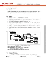
Block Diagram
18-bit WDT Counter
0
… ... 15
..
4
16 17
000
001
110
111
:
:
WDT_CLK [Note 2]
Time-
Out
Interval
Period
select
Reset
Delay
Period
Select
[Note 3]
Watchdog
Interrupt
Watchdog
Reset [Note 1]
RSTCNT(WDT_CTL[0])
Reset WDT
Counter
WDTEN
(WDT_CTL[7])
Wakeup CPU from
Power - down mode
TOUTSEL
(WDT_CTL[10:8])
IF
(WDT_CTL[3])
INTEN
(WDT_CTL[6])
RSTEN
(WDT_CTL[1])
RSTF
(WDT_CTL[2])
WKEN
(WDT_CTL[4])
WKF
(WDT_CTL[5])
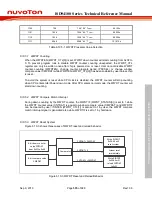
Figure 6.9-1 Watchdog Timer Block Diagram
Note1:
WDT resets CPU and lasts 63 WDT_CLK.
Note2:
Chip can be woken-up by WDT time-out interrupt signal generated only,
if WDT clock source is selected to 10 kHz oscillator.
Note3:
The WDT reset delay period can be selected as 3/18/130/1026 WDT_CLK.
6.9.4
Basic Configuration
Clock source configuration
–
Select the source of WDT peripheral clock on WDTSEL (CLK_CLKSEL1[1:0])

