ISD94100 Series Technical Reference Manual
Sep 9, 2019
Page
422
of 928
Rev1.09
IS
D
9
410
0
S
ER
IE
S
T
E
C
HN
ICA
L
RE
F
E
RE
NCE
M
AN
U
AL
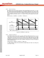
function makes any channel of PWM0 in phase, user can control phase value and direction.
6.8.5.18 Group function
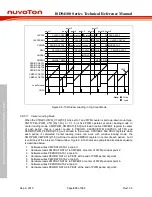
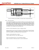
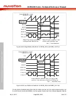
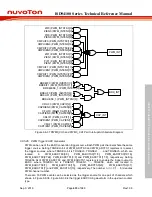
Group function is enabled when GROUPEN (PWM_CTL0[24]) is set to 1, no matter in independent
or complementary mode. This control allows all even PWM channels output to be controllable by
PWM_PERIOD0 and PWM_CMPDAT0 registers and all odd PWM channels output to be
controllable by PWM_PERIOD1 and PWM_CMPDAT1 registers. That is, user only needs to set
PWM_CH0 to get PWM_CH0, PWM_CH2 and PWM_CH4 output the same pulse, and set
PWM_CH1 to get PWM_CH1, PWM_CH3 and PWM_CH5 output the same pulse, as shown in
Figure 6.8-22. When operating group function, OUTMODE0, OUTMODE2 and OUTMODE4 bits of
PWM_CTL1 register must all set to 0 for independent mode or all set to 1 for complementary mode.
PWM_CH2
PWM_CH0
Setting:
OUTMODE0 (PWM_CTL1[24]) = 0x1
PWM_CH1
PWM_CH3
PWM_CH4
PWM_CH5
Setting:
OUTMODE2 (PWM_CTL1[25]) = 0x1
Setting:
OUTMODE4 (PWM_CTL1[26]) = 0x1
Setting:
GROUPEN (PWM_CTL0[24]) = 0x1
Figure 6.8-22 PWM Group Function Waveform
6.8.5.19 Synchronous function
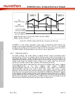
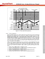
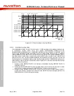
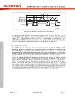
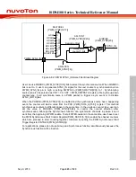
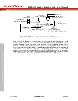
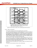
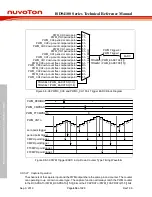
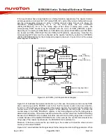
Synchronous function can only be enabled when complementary mode is enabled. Figure 6.8-24
is counter synchronous function block diagram. Every counter of PWM pairs has a SYNC_IN and
a SYNC_OUT signals. The SYNC_IN signal for the first PWM0 pair counter comes from
PWM0_SYNC_IN pin, and the others come from the SYNC_OUT signal of the previous PWM pair
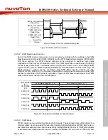
counter. The input signal from PWM0_SYNC_IN pin will be filtered by a 3-bit noise filter as Figure
6.8-23. In addition, it can be inversed by setting the bit SINPINV (PWM_SYNC[23]) to realize the
polarity setup for the input signal. The noise filter sampling clock can be selected by setting bits
SFLTCSEL (PWM_SYNC[19:17]) to fit different noise properties. Moreover, by setting the bits
SFLTCNT (PWM_SYNC[22:20]), user can define by how many sampling clock cycles a filter will
recognize the effective edge of the SYNC_IN signal. Configuring the SNFLTEN (PWM_SYNC[16])
will enable the noise filter function. By default, it is disabled.


