ISD94100 Series Technical Reference Manual
Sep 9, 2019
Page
34
of 928
Rev1.09
IS
D
9
410
0
S
ER
IE
S
T
E
C
HN
ICA
L
RE
F
E
RE
NCE
M
AN
U
AL
4.4
Pin Description
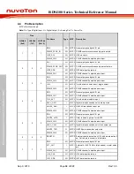
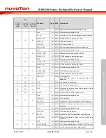
MFP = Multi-function pin.
Note:
Pin Type I=Digital Input, O = Digital Output; A = Analog Pin; P = Power Pin;
Pins
Pin Name
Type MFP
Description
QFN48
(6x6)
LQFP64
(7x7)
LQFP64
(10x10)
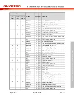
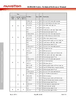
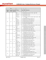
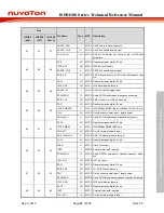
1
1
1
PB.0
I/O
MFP0 General purpose digital I/O pin.
PWM0_SYNC_IN
I/O
MFP1 PWM0 counter synchronous trigger input pin.
I2C0_SCL
I/O
MFP2 I2C0 clock pin.
PWM0_CH0
I/O
MFP3 PWM0 channel0 output/capture input.
2
2
2
PB.1
I/O
MFP0 General purpose digital I/O pin.
PWM0_SYNC_OUT
I/O
MFP1 PWM0 counter synchronous trigger output pin.
I2C0_SDA
I/O
MFP2 I2C0 data input/output pin.
PWM0_CH1
I/O
MFP3 PWM0 channel1 output/capture input.
3
3
3
PB.2
I/O
MFP0 General purpose digital I/O pin.
PWM0_CH0
I/O
MFP1 PWM0 channel0 output/capture input.
TM2
I/O
MFP2 Timer2 event counter input / toggle output.
PWM0_CH2
I/O
MFP3 PWM0 channel2 output/capture input.
4
4
4
PB.3
I/O
MFP0 General purpose digital I/O pin.
PWM0_CH1
I/O
MFP1 PWM0 channel1 output/capture input.
TM2_EXT
I/O
MFP2 Timer2 external capture input.
DMIC_DAT1
I
MFP3 Digital microphone channel 1 data input pin.
UART0_RXD
I
MFP4 UART0 Data receiver input pin.
PWM0_CH3
I/O
MFP5 PWM0 channel3 output/capture input.
5
5
5
PB.4
I/O
MFP0 General purpose digital I/O pin.
UART0_nCTS
I
MFP1 Clear to Send input pin for UART0.
PWM0_CH0
I/O
MFP2 PWM0 channel0 output/capture input.
DMIC_CLK1
O
MFP3 Digital microphone channel 1 clock output pin.
UART0_TXD
O
MFP4 UART0 data transmitter output pin.
PWM0_CH4
I/O
MFP5 PWM0 channel4 output/capture input.
6
6
6
RESETN
I
MFP0 External reset input: active LOW, with an internal pull-
up. Set this pin low reset to initial state.
7
7
7
PB.5
I/O
MFP0 General purpose digital I/O pin.
XT1_OUT
I
MFP1 External 4~24.576 MHz (high speed) crystal output
pin.
PWM0_CH1
I/O
MFP2 PWM0 channel1 output/capture input.
I2C0_SDA
I/O
MFP3 I2C0 data input/output pin.
I2C1_SDA
I/O
MFP4 I2C1 data input/output pin.

