ISD94100 Series Technical Reference Manual
Sep 9, 2019
Page
697
of 928
Rev1.09
IS
D
9
410
0
S
ER
IE
S
T
E
C
HN
ICA
L
RE
F
E
RE
NCE
M
AN
U
AL
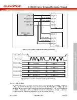
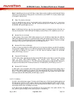
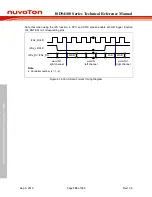
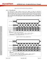
Master mode reception operation. If the receive FIFO buffer contains 4 (or 8 for SPI0) unread
data, the RXFULL (SPIn_STATUS[9]) will be set to 1 and the RXOVIF (SPIn_STATUS[11]) will be
set to 1 if there is more serial data received from SPI0_MOSI0 and SPIx_MOSI (x=1, 2) pin and
follow-up data will be dropped (refer to the Receive FIFO Buffer Example figure). If the receive bit
count mismatch with the DWIDTH (SPIn_CTL[12:8]) when the slave selection line goes to inactive
state, the SLVBEIF (SPIn_STATUS[6]) will be set to 1.
SPIx_SSy pin
(SSACTPOL = 0)
SPIx_CLK pin
Data width
SLVBEIF
DWIDTH = 16
1
2
3
4
5
6
7
8
Reveive Bit
Counter
0
Receive bit count !=
DWIDTH
Note:
x: Controller number (x = 0, 1, 2), y: Slave select pin channel number in SPI0 (y = 0, 1)
Figure 6.14-28 Slave Mode Bit Count Error
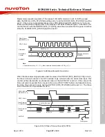
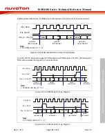
When the Slave select signal is active and the value of SLVTOCNT (SPI0_SSCTL[31:16]) is not 0,
the Slave time-out counter in the SPI controller logic will start after the serial clock input. This
counter will be cleared after one transaction done or the SLVTOCNT is set to 0. If the value of the
time-out counter is greater than or equal to the value of SLVTOCNT before one transaction done,
the slave time-out event occurs and the SLVTOIF (SPI0_STATUS[5]) will be set to 1. The Slave
time-out function is only available for SPI0.
SPI0_SS0/1 pin
(SSACTPOL = 0)
SPI0_CLK pin
Slave Time-out
Counter Setting
SLVTOIF
SLVTOCNT = 256
Slave Time-out
Counter
0
Clear by user
123456
(n)(n+1) 0
123456
(n)(n+1)
(255)(256)(256)(256)
0
0
Clear by Slave Selection inactive signal
Figure 6.14-29 Slave Time-out Event (for SPI0)


