ISD94100 Series Technical Reference Manual
Sep 9, 2019
Page
624
of 928
Rev1.09
IS
D
9
410
0
S
ER
IE
S
T
E
C
HN
ICA
L
RE
F
E
RE
NCE
M
AN
U
AL
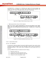
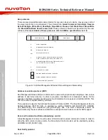
one Read/Write bit – in this case it is ‘0’ indicating a write operation. The second address byte
contains the lower 8-bit address. The master keeps sending data after addressing byte
acknowledged. The 7-bit and 10-bit address devices can work on the same bus.
‘0’ : write
S
ADDRESS 1st byte
R/W
A
DATA
A
DATA
A/A
P
data transfer
(n bytes + acknowlegde)
ADDRESS 2nd byte
A
...
...
11110XX
Figure 6.13-10 Master Transmits Data to Slave
by 10-bit
•
Master reads data from a slave with 10-bit address
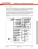
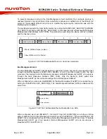
Figure 6.13-11 shows a master reading data from a slave with 10-bit address. First the master
needs to send 10-bit addressing bits with R/W bit as 0 in the first header byte; then the master
needs to send the second header byte only with R/W bit as 1 to indicate this is a master read
operation.
...
‘1’ : read
Sr
ADDRESS 1st byte
R/W
A
DATA
A
DATA
A/A
P
data transfer
(n bytes + acknowlegde)
‘0’ : write
S
ADDRESS 1st byte
R/W
A
ADDRESS 2nd byte
A
11110XX
11110XX
Figure 6.13-11 Master Reads Data from Slave by 10-bit
6.13.5.2 Operational Description
6.13.5.2.1 I2C Initialization
An interrupt driven process is suitable for handling the ISD94100 series I2C communication. When
working as a master, the ISD94100 series device generates a START condition, then responds to
the following interrupts; in slave mode, after I2C initialization the device simply waits for I2C
interrupts.
Typically the ISD94100 series I2C initialization does the following:
Enable I2C module clock
Configure I2C clock speed, enable I2C module
Enable I2C interrupt, and initialize I2C NVIC vector
Configure its own the slave address register.


