ISD94100 Series Technical Reference Manual
Sep 9, 2019
Page
545
of 928
Rev1.09
IS
D
9
410
0
S
ER
IE
S
T
E
C
HN
ICA
L
RE
F
E
RE
NCE
M
AN
U
AL
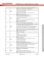
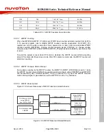
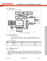
6.11.3 Block Diagram
The RTC block diagram is shown below.
RTC Time Counter
Control Unit
Time Loading
Register
(RTC_TIME)
Calendar
Loading
Register
(RTC_CAL)
Time Alarm
Register
(RTC_TALM)
Calendar
Alarm Register
(RTC_CALM)
1/128 change
1/64 change
1/32 change
1/16 change
1/8 change
1/4 change
1/2 change
1 change
(sec)
111
110
101
100
011
010
001
000
TICK (RTC_TICK[2:0])
TICKIF (RTC_INTSTS[1])
TICKIEN (RTC_INTEN[1])
Compare
Operation
ALMIEN (RTC_INTEN[0])
Alarm Interrupt
RTC_CLK
Frequency
Compensation
Frequency
Compensation
Register
(RTC_FREQADJ)
RWEN
WEEKDAY
LEAPYEAR
24H/12H
ALMIF (RTC_INTSTS[0])
Wakeup CPU from
Power-down mode
Tick Interrupt
Time Alarm
Mask Register
(RTC_TAMSK)
Calendar Alarm
Mask Register
(RTC_CAMSK)
LIRC
0
1
RTCSEL
(CLK_CLKSEL3[8])
LXT
INIT
INIT
RWEN
LEAPYEAR
CLKFMT
WEEKDAY
Figure 6.11-1 RTC Block Diagram
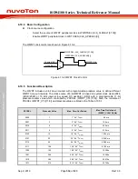
6.11.4 Basic Configuration
Clock source configuration
–
The RTC controller clock source is enabled by RTCCKEN (APBCLK0[1]) and RTC
Time Counter source is selected by CLK_CLKSEL3[8], the clock source can be LXT or
LIRC.
Pin configuration
Group
Pin Name
GPIO
MFP
X32
X32_OUT
PC.0
MFP2
X32_IN
PC.1
MFP2
6.11.5 Functional Description
6.11.5.1 RTC Initiation
When a RTC block is power-on, RTC is at reset state. User has to write a number 0xa5eb1357 to
RTC initial register INIT(RTC_INIT[31:0]) to make RTC leaving reset state. Once the
INIT(RTC_INIT[31:0]) register is written as 0xa5eb1357, the RTC will be in normal active state
permanently. User can read INIT[0](RTC_INIT[0]) to check the RTC is at normal active state or
reset state.

