ISD94100 Series Technical Reference Manual
Sep 9, 2019
Page
240
of 928
Rev1.09
IS
D
9
410
0
S
ER
IE
S
T
E
C
HN
ICA
L
RE
F
E
RE
NCE
M
AN
U
AL
6.5
General Purpose I/O (GPIO)
6.5.1
Overview
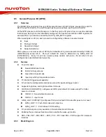
The ISD94100 series device has up to 58 General Purpose I/O (GPIO) pins, grouped in 4 ports PA,
PB, PC and PD. Port PA, PC and PD each has 16 pins, and there are 13 pins in Port PB.
All the GPIO pins are multi-functional pins, in that they can be I/O pins or they can work as alternate
function pins. Each pin can be individually configured. Pin function are defined in MFP registers, for
example PA0~7 pin functions are defined in SYS_GPA_MFPL register.
When working as an I/O pin, each pin can be configured by software in several modes:
Input
Push-pull Output
Open-Drain Output
Quasi-bidirectional
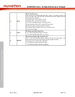
After a power-on or reset event, all GPIO pins’ default working mode are determined by CIOINI bit
(CONFIG0[10]) except PA.8. PA.8 pin default I/O mode is determined by GPA8_LOW bit
(CONFIG0[11]). Every I/O pin has a weak pull-up resistor with value ~50 k
Ω
when I/O pin
configured as quasi-bidirectional output low.
6.5.2
Features
Four I/O modes:
Quasi-bidirectional mode
Push-Pull Output mode
Open-Drain Output mode
Input only with high impendence mode
TTL/Schmitt trigger input capability
I/O pin can be configured as interrupt source with edge/level trigger option
Supports High Drive and High Slew Rate I/O mode
CIOINI bit (CONFIG0[10]) configures all GPIO pins’ default I/O mode except PA.8 after
power-on or reset:
CIOINI = 0: Quasi-bidirectional mode,
CIOINI = 1: input mode.
GPA8_LOW (CONFIG[11]) configures PA.8 pin’s default I/O mode after power-on or reset:
GPA8_LOW = 0: Push-Pull mode and output low,
GPA8_LOW = 1: PA.8 follows CIOINI setting.
I/O pin internal pull-up only available in Quasi-bidirectional I/O mode
Enabling the pin interrupt function will also enable the wake-up function
PB0 ~ PB4, PB7 ~ PB9, PB13 ~ PB15, PC2 ~ PC15 and PD0 ~ PD15 support 5V-tolerance
functions
6.5.3
Block Diagram

