ISD94100 Series Technical Reference Manual
Sep 9, 2019
Page
132
of 928
Rev1.09
IS
D
9
410
0
S
ER
IE
S
T
E
C
HN
ICA
L
RE
F
E
RE
NCE
M
AN
U
AL
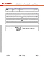
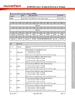
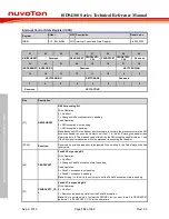
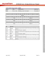
Interrupt Control State Register (ICSR)
Register
Offset
R/W Description
Reset Value
ICSR
0xD04
R/W Interrupt Control and State Register
0x0000_0000
31
30
29
28
27
26
25
24
NMIPENDSET
Reserved
PENDSVSET
PENDSVRTC_
CAL
PENDSTSET
PENDSTRTC_
CAL
Reserved
23
22
21
20
19
18
17
16
ISRPREEMPT ISRPENDING
Reserved
VECTPENDING
15
14
13
12
11
10
9
8
VECTPENDING
RETTOBASE
Reserved
7
6
5
4
3
2
1
0
Reserved
VECTACTIVE
Bits
Description
[31]
NMIPENDSET
NMI Set-pending Bit
Write Operation:
0 = No effect.
1 = Changes NMI exception state to pending.
Read Operation:
0 = NMI exception is not pending.
1 = NMI exception is pending.
Note:
Because NMI is the highest-priority exception, normally the processor enters the NMI
exception handler as soon as it detects a write of 1 to this bit. Entering the handler then
clears this bit to 0. This means a read of this bit by the NMI exception handler returns 1 only
if the NMI signal is reasserted while the processor is executing that handler.
[30:29]
Reserved
Reserved. Any values read should be ignored. When writing to this field always write with
reset value.
[28]
PENDSVSET
PendSV Set-pending Bit
Write Operation:
0 = No effect.
1 = Changes PendSV exception state to pending.
Read Operation:
0 = PendSV exception is not pending.
1 = PendSV exception is pending.
Note:
Writing 1 to this bit is the only way to set the PendSV exception state to pending.
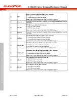
[27]
PENDSVRTC_CA
L
PendSV Clear-pending Bit
Write Operation:
0 = No effect.
1 = Removes the pending state from the PendSV exception.
Note:
This is a write only bit. To clear the PENDSV bit, you must “write 0 to PENDSVSET
and write 1 to PENDSVRTC_CAL” at the same time.


