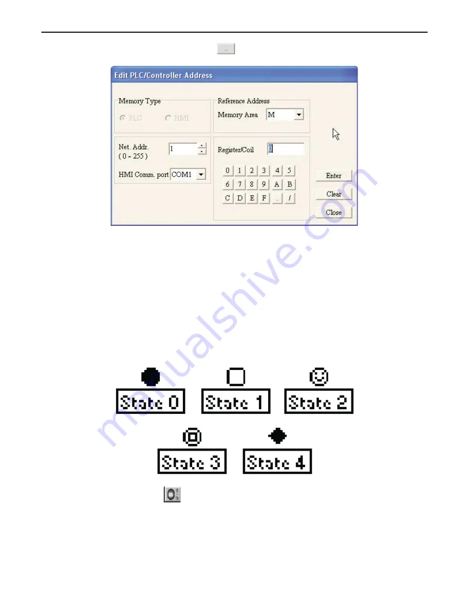
PLC/Controller Address button
to display the Edit PLC/Controller Address dialog
box:
\
3. In the Reference Address area, click the pull-down box to select the
target PLC memory area
. Use the
numeric keypad to enter the specific
PLC memory address
. Select the
PLC Network Address
(if
applicable) and
HMI communications port
. Click
Enter
to go back to prior dialog box.
4. In the
Bitmap Setting
frame, select which
Bit Lamp object
to display for the ON state and the OFF
state. There are eighteen predefined bitmaps from which to select from (to use a custom bitmap or text
labels, you must use the Multi-State Bitmap w/Label object).
5. Click
OK
. The Bit Lamp Object is displayed on the main screen of BlueLeaf with the appropriate
bitmap displayed. If necessary, use the mouse to drag the part to the location on the window that you
want it. Note: the Bit Lamp object is always preset to 16x16 pixels in size and cannot be changed.
The Word Lamp Object
The Word Lamp Object is used to represent the value of a PLC data register. The object continuously reads the PLC register
and displays the corresponding bitmap that is tagged to each state of the register. A maximum of five states can be created, as
shown in the example below:
4
To create a Word Lamp Object
1. From the
OBJECTS
menu, click
Word Lamp
. Or click the
Word Lamp
icon in the Objects toolbar.
The mouse cursor changes to a crosshair. Select the location on the screen to place the Word Lamp
1010-0300, Rev 02
84
Blue Series Installation & Operation Manual


