Trigger
Condition
Description
Example
=
Equal condition
4x1 = 5: if value in register 4x1 is equal to
5, activate LED.
>
Greater than condition
4x1 > 5: if value in register 4x1 is greater
than 5, activate LED.
<
Less than condition
4x1 < 5: if value in register 4x1 is smaller
than 5, activate LED.
>=
Greater than or equal to
4x1 >= 5: if value in register 4x1 is greater
than or equal to 5, activate LED
<=
Less than or equal to
4x1 <= 5: if value in register 4x1 is less than
or equal to 5, activate LED
!=
Not equal
4x1 != 5: if value in register 4x1 is not 5,
activate LED.
7. In the
PLC/Controller Address
frame, enter the
PLC coil
or
register address
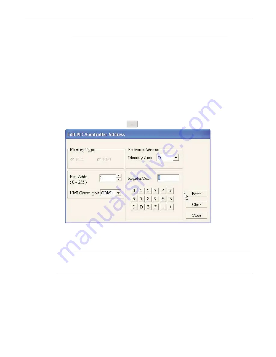
. Or click the
PLC/Controller Address button
to display the Edit PLC/Controller Address dialog box:
8. In the reference address area, click the pull-down box to select the
target PLC memory area.
Use the
numeric keypad to enter the specific
PLC memory address
. Select the
PLC Network Address
(if
applicable) and
HMI communications port
. Click
Enter
to go back to prior dialog box.
9. Click
OK
to go back to the main screen of BlueLeaf. To delete an Alarm Buzzer, click the
Cancel Set
button.
*
When using the Local Alarm Buzzer and a Global Alarm Buzzer, the Alarm Buzzer will activate
and remain active if either condition is true. If a Local Alarm Buzzer is used, the Alarm Buzzer
will turn off if a new screen is displayed on the OIT, regardless of whether or not the Local
Alarm condition is still true.
Displaying Alarms using the Dynamic Message Object
Though the Dynamic Message object can be used to display any messages, it is particularly useful for displaying warning
messages and instructions that are tied to an alarm condition. Similar to the Alarm LED and Alarm Buzzer, you can
construct a dynamic message object that changes messages according to a PLC coil or register value.
1010-0300, Rev 02
Using Alarms
127


